Description
RF-IN
RF-OUT and DC-IN
4
GROUND
3 RF-OUT & DC-IN 2 GROUND 1 RF-IN
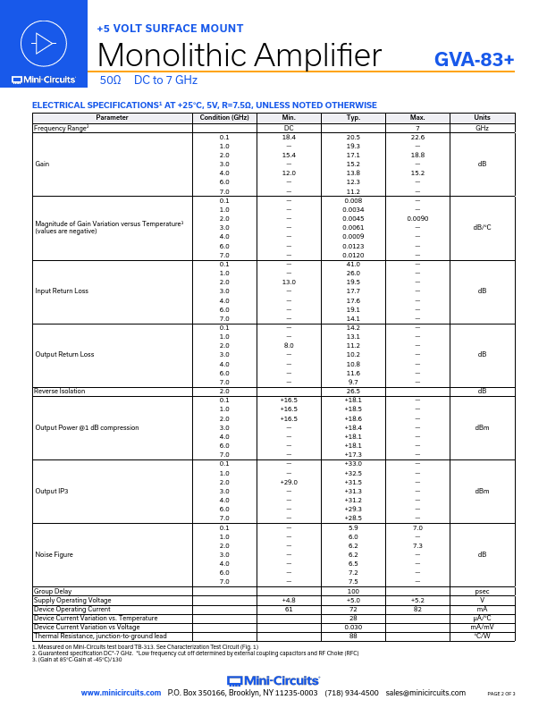
Function
Pin Number
Description
RF-IN
1
RF input pin.This pin requires the use of an external DC blocking capacitor chosen for the frequency of operation.RF-OUT and DC-IN
3
RF output and bias pin.DC voltage is present on this pin; therefore a DC blocking capacitor is necessary for proper operation.An RF choke is needed to feed DC bias without loss of RF signal due to the bias connection, as shown in “Recommended
Features
- y High Gain, 20 dB typ. at 100 MHz y High POUT, P1dB 18 dBm typ. y High IP3, +33 dBm typ. at 100 MHz y Ruggedized Design y +5V operation y Unconditionally stable y Excellent ESD Protection y Transient protected, US patent 6,943,629
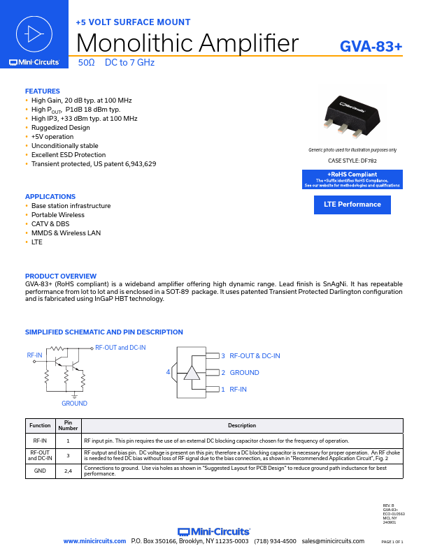
Generic photo used for illustration purposes only CASE STYLE: DF782.
 GVA-83_Mini-Circuits.pdf