MFE121 Description
Vqs = 0) Gate 1 to Source Cutpff Voltage (V DS = 15 Vdc, VQ2S = 40 vdc, Id = 200 MAdc) Gate 2 to Source Cutoff Voltage (Vds = 15 Vdc, Vqis = 0, Id = 200 ,iAdc) ON CHARACTERISTICS Zero-Gate-Voltage.
| Part number | MFE121 |
|---|---|
| Download | MFE121 Datasheet (PDF) |
| File Size | 117.92 KB |
| Manufacturer | Motorola Semiconductor |
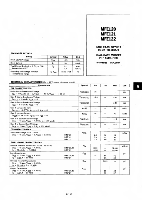
| Description | DUAL-GATE MOSFET VHF AMPLIFIER |
|
|
| Manufacturer | Part Number | Description |
|---|---|---|
| MFE121 | DUAL GATE MOSFETS |
Vqs = 0) Gate 1 to Source Cutpff Voltage (V DS = 15 Vdc, VQ2S = 40 vdc, Id = 200 MAdc) Gate 2 to Source Cutoff Voltage (Vds = 15 Vdc, Vqis = 0, Id = 200 ,iAdc) ON CHARACTERISTICS Zero-Gate-Voltage.