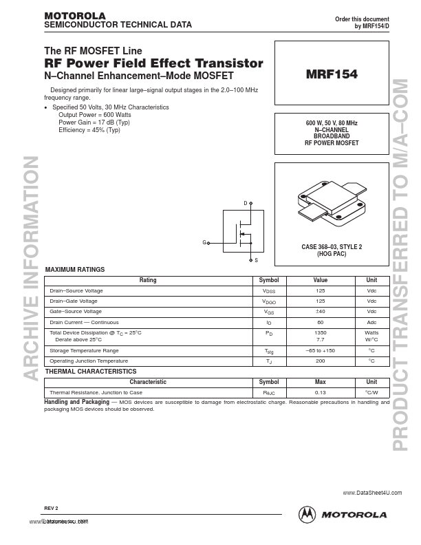
Datasheet4U Logo Datasheet4U.com

MRF154 - N-CHANNEL BROADBAND RF POWER MOSFET

Features

  • stages of handling or during transportation. It is recommended that the user makes a final inspection on this before the device installation. ±0.0005″ is considered sufficient for the flange bottom. The same applies to the heat dissipator in the device mounting area. If copper heatsink is not used, a copper head spreader is strongly recommended between the device mounting surfaces and the main heatsink. It should be at least 1/4″ thick and extend at least one inch from the flange edges. A thin l.

📥 Download Datasheet

Other Datasheets by Motorola

Full PDF Text Transcription

Click to expand full text
( DataSheet : www.DataSheet4U.com ) MOTOROLA SEMICONDUCTOR TECHNICAL DATA Order this document by MRF154/D The RF MOSFET Line RF Power Field Effect Transistor N–Channel Enhancement–Mode MOSFET Designed primarily for linear large–signal output stages in the 2.0–100 MHz frequency range. • Specified 50 Volts, 30 MHz Characteristics Output Power = 600 Watts Power Gain = 17 dB (Typ) Efficiency = 45% (Typ) 600 W, 50 V, 80 MHz N–CHANNEL BROADBAND RF POWER MOSFET D G S CASE 368–03, STYLE 2 (HOG PAC) MAXIMUM RATINGS Rating Drain–Source Voltage Drain–Gate Voltage Gate–Source Voltage Drain Current — Continuous Total Device Dissipation @ TC = 25°C Derate above 25°C Storage Temperature Range Operating Junction Temperature Symbol VDSS VDGO VGS ID PD Tstg TJ Value 125 125 ±40 60 1350 7.
Published: |