MRF154 Overview
Key Features
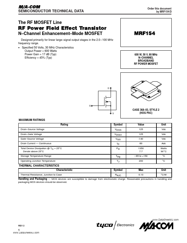
- Channel Enhancement
- Specified 50 Volts, 30 MHz Characteristics Output Power = 600 Watts Power Gain = 17 dB (Typ) Efficiency = 45% (Typ) Designed primarily for linear large
| Part | MRF154 |
|---|---|
| Description | N-CHANNEL BROADBAND RF POWER MOSFET |
| Category | MOSFET |
| Manufacturer | Tyco Electronics |
| Size | 226.85 KB |
| Part Number | Manufacturer | Description |
|---|---|---|
| MRF154 | MACOM Technology Solutions | Broadband RF Power MOSFET |
| MRF154 | Motorola Semiconductor | N-CHANNEL BROADBAND RF POWER MOSFET |
| MRF150 | Advanced Semiconductor | SILICON RF POWER MOSFET |
| MRF1570FNT1 | Freescale Semiconductor | RF Power Field Effect Transistors |
| MRF150 | MACOM Technology Solutions | RF Power FET |