MRF154 Overview
Key Features
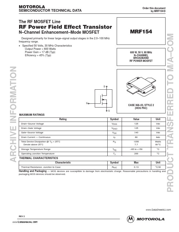
- Channel Enhancement
- signal output stages in the 2.0
| Part | MRF154 |
|---|---|
| Description | N-CHANNEL BROADBAND RF POWER MOSFET |
| Category | MOSFET |
| Manufacturer | Motorola Semiconductor |
| Size | 195.40 KB |
| Part Number | Manufacturer | Description |
|---|---|---|
| MRF154 | Tyco Electronics | N-CHANNEL BROADBAND RF POWER MOSFET |
| MRF154 | MACOM Technology Solutions | Broadband RF Power MOSFET |
| MRF150 | Advanced Semiconductor | SILICON RF POWER MOSFET |
| MRF1570FNT1 | Freescale Semiconductor | RF Power Field Effect Transistors |
| MRF150 | MACOM Technology Solutions | RF Power FET |