2SC5007
2SC5007 is NPN TRANSISTOR manufactured by NEC.
DESCRIPTION
The 2SC5007 is an NPN epitaxial silicon transistor designed for use in low noise and small signal amplifiers from VHF band to UHF band. Low noise figure, high gain, and high current capability achieve a very wide dynamic range and excellent linearity. This is achieved by direct nitride passivated base surface, process (NEST2 process) which is an NEC proprietary fabrication technique.
FEATURES
- Low Voltage Use.
- High f T
- Low Cre
- Low NF : 7.0 GHz TYP. (@ VCE = 3 V, IC = 7 m A, f = 1 GHz) : 0.45 p F TYP. (@ VCE = 3 V, IE = 0, f = 1 MHz) : 1.4 d B TYP. (@ VCE = 3 V, IC = 7 m A, f = 1 GHz)
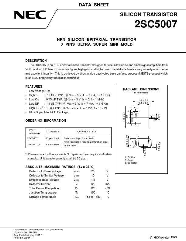
0.5 1.6 ± 0.1 1.0 0.2+0.1
- 0 0.3 +0.1
- 0 0.15
+0.1
- 0.05
PACKAGE DIMENSIONS in millimeters 1.6 ± 0.1 0.8 ± 0.1
- High |S21e|2 : 12 d B TYP. (@ VCE = 3 V, IC = 7 m A, f = 1 GHz)
- Ultra Super Mini Mold Package.
ORDERING INFORMATION
PART NUMBER 2SC5007 2SC5007-T1
QUANTITY 50 pcs./Unit 3 kpcs./Reel PACKING STYLE Embossed tape 8 mm wide. Pin3 (Collector) face to perforation side of the tape.
0.75 ± 0.05
- Please contact with responsible NEC person, if you require evaluation sample. Unit sample quantity shall be 50 pcs.
1. Emitter 2. Base 3. Collector
ABSOLUTE MAXIMUM RATINGS (TA = 25 ˚C)
Collector to Base Voltage Collector to Emitter Voltage Emitter to Base Voltage Collector Current Total Power Dissipation Junction Temperature Storage Temperature VCBO VCEO VEBO IC PT Tj Tstg 20 10 1.5 65 125 150
- 65 to +150 V V V m A m W ˚C ˚C
Document No. P10386EJ2V0DS00 (2nd edition) (Previous No. TD-2400) Date Published July 1995 P Printed in Japan
0 to 0.1
©
ELECTRICAL CHARACTERISTICS (TA = 25 ˚C)
CHARACTERISTIC Collector Cutoff Current Emitter Cutoff Current DC Current Gain Gain Bandwidth Product Feed-Back Capacitance Insertion Power Gain Noise Figure SYMBOL ICBO IEBO h FE f T Cre |S21e|2 NF 10.0 80 4.5 7.0 0.45 12.0 1.4 2.7 0.9 MIN. TYP. MAX. 0.8 0.8 160 GHz p F d B d B UNIT TEST CONDITIONS VCB = 10 V, IE = 0 VEB = 1 V, IC = 0 VCE = 3 V, IC = 7 m A- 1 VCE...