MRF8S9200NR3
MRF8S9200NR3 is RF Power Field Effect Transistor manufactured by NXP Semiconductors.
Features
- 100% PAR Tested for Guaranteed Output Power Capability
- Characterized with Series Equivalent Large--Signal Impedance Parameters and mon Source S--Parameters
- Internally Matched for Ease of Use
- Integrated ESD Protection
- Greater Negative Gate--Source Voltage Range for Improved Class C
Operation
- 225°C Capable Plastic Package
- Designed for Digital Predistortion Error Correction Systems
- Optimized for Doherty Applications
- Ro HS pliant
- In Tape and Reel. R3 Suffix = 250 Units per 32 mm, 13 inch Reel.
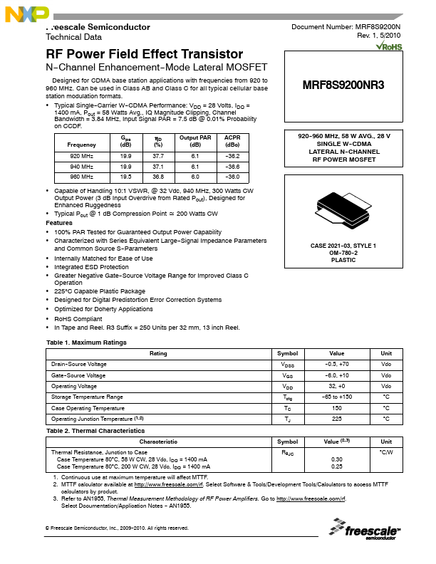
CASE 2021--03, STYLE 1 OM--780--2 PLASTIC
Table 1. Maximum Ratings
Rating
Symbol
Value
Unit
Drain--Source Voltage Gate--Source Voltage Operating Voltage Storage Temperature Range Case Operating Temperature Operating Junction Temperature (1,2)
VDSS
--0.5, +70
Vdc
--6.0, +10
Vdc
32, +0
Vdc
Tstg
--65 to +150
°C
°C
°C
Table 2. Thermal Characteristics
Characteristic
Symbol
Value...