PDTC124ES Overview
Key Specifications
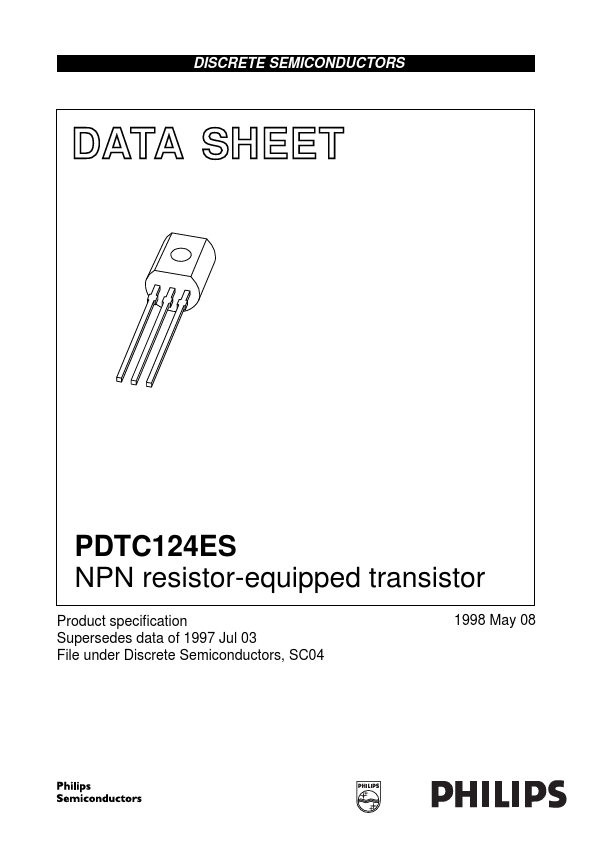
Package: TO-226-3
Mount Type: Through Hole
Pins: 3
Max Operating Temp: 150 °C
Key Features
- Built-in bias resistors R1 and R2 (typ. 22 kΩ each)
- Simplification of circuit design
- Reduces number of components and board space. APPLICATIONS
- Especially suitable for space reduction in interface and driver circuits
- 60 15.4 0.8 MIN