Datasheet Details
| Part number | 74F410 |
|---|---|
| Manufacturer | National |
| File Size | 151.67 KB |
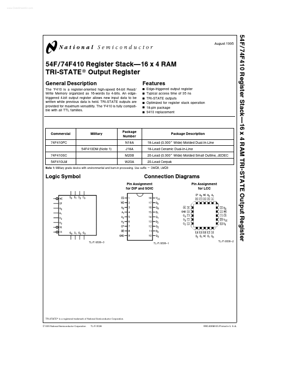
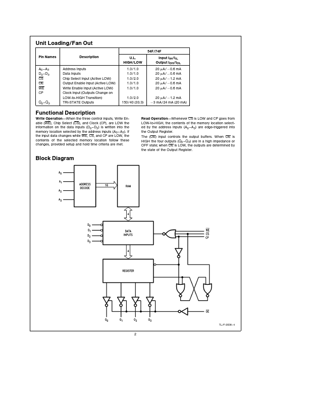
| Description | Register Stack16 x 4 RAM TRI-STATEE Output Register |
| Datasheet |
 74F410 Datasheet 74F410 Datasheet
|
|
|
| Part number | 74F410 |
|---|---|
| Manufacturer | National |
| File Size | 151.67 KB |
| Description | Register Stack16 x 4 RAM TRI-STATEE Output Register |
| Datasheet |
74F410 Datasheet
|
|
|
|
| Part Number | Description | Manufacturer |
|---|---|---|
| 74F410 | Register stack . 164 RAM 3-State output register | Philips |
| 74F413 | 64 x 4 First-In First-Out Buffer Memory | Fairchild |
| 74F40 | Dual 4-input NAND buffer | Philips |
| 74F401 | CRC Generator/Checker | Fairchild |
| 74F402 | Serial Data Polynomial Generator/Checker | Fairchild |
| Part Number | Description |
|---|---|
| 74F413 | 64 x 4 First-In First-Out Buffer Memory |
| 74F402 | Serial Data Polynomial Generator/Checker |
| 74F181 | 4-Bit Arithmetic Logic |
| 74F182 | Carry Lookahead Generator |
| 74F189 | 64-Bit RAM |
The following content is an automatically extracted verbatim text from the original manufacturer datasheet and is provided for reference purposes only.