74ACT244 Overview
Description
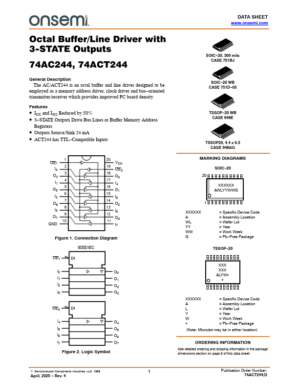
The AC/ACT244 is an octal buffer and line driver designed to be employed as a memory address driver, clock driver and bus-oriented transmitter/receiver which provides improved PC board density.
Key Features
- ICC and IOZ Reduced by 50%
- 3-STATE Outputs Drive Bus Lines or Buffer Memory Address Registers
- Outputs Source/Sink 24 mA