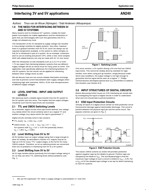
• Part: AN240
  • Description: Interfacing 3V and 5V Applications
  • Manufacturer: Philips Semiconductors
  • Size: 62.60 KB
Download AN240 Datasheet PDF
Philips Semiconductors
AN240
AN240 is Interfacing 3V and 5V Applications manufactured by Philips Semiconductors.
features can only be made with 3V. Or vice versa! With the introduction of new standards such as 2.2-2.7V or even 1.7V we expect that interfacing between systems that use different supply voltages will be an actual issue for many years to e. This application note specifically addresses the interfacing between 3V and 5V systems, but the results can be applied for interfacing between other voltage levels as well. We will discuss how one can ensure reliable information exchange and how to prevent current flow between both supply voltages when interfacing logic with memories, ASICs, PLDs and microprocessors at different supply voltages. CMOS LEVELS VCC TTL LEVELS 70% 3.3V OUTPUT 30% 2V 0.8V GND SV00084 Figure 1. Switching Levels One issue remains: a 3V system driving a 5V one that has CMOS input levels. This cannot be reliably done by standard 3V logic families, even when using pull-up resistors, simply because under worst case conditions, the output voltage is not high enough to guarantee that the signal will be seen as a logical “1”. Philips Semiconductors developed special dual VCC levelshifters to address that situation (see Section 6.0). 2.0 LEVEL SHIFTING - INPUT AND OUTPUT LEVELS We obviously want a reliable signal transfer from the 5V system to the 3V system and vice versa. This implies that the output voltages should be such that the input levels are exceeded. 3.0 INPUT STRUCTURES OF DIGITAL CIRCUITS Before discussing further issues on 3-5V interfacing we should start by investigating the inputs of digital circuits in order to understand what care one should take to prevent problems. 3.1 ESD Input Protection Circuits Virtually all inputs of a digital circuit contain an ESD protection circuit that prevents damage against electrostatic discharge. This circuit is present between the physical input pin and the active circuit. Two popular schemes are given in Fig. 2. 2.1 TTL and CMOS Switching Levels As a reminder, digital circuits have input...