MG6303WZ Overview
Key Features
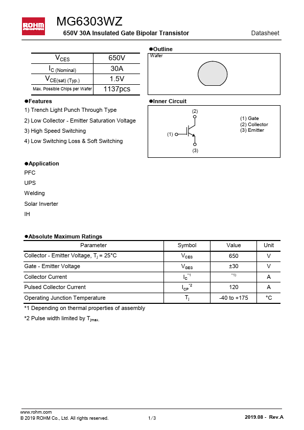
- Low Collector
- Emitter Saturation Voltage
- High Speed Switching
- Low Switching Loss & Soft Switching
| Part | MG6303WZ |
|---|---|
| Description | Insulated Gate Bipolar Transistor |
| Category | Transistor |
| Manufacturer | ROHM |
| Size | 455.18 KB |
| Part Number | Manufacturer | Description |
|---|---|---|
| MG630 | Matrixopto | GaAs Hall Element |