L6232B
L6232B is SPINDLE DRIVER manufactured by STMicroelectronics.
1.5A MAXIMUM PEAK CURRENT CONTROLLED SLEW RATE CENTRAL CHARGE PUMP PWM AND LINEAR MODES CUTOFF TIME USER CONFIGURABLE FAST, FREE-WHEELING DIODES ON CHIP OVER-TEMPERATURE PROTECTION BRAKE FUNCTION INPUT
DESCRIPTION
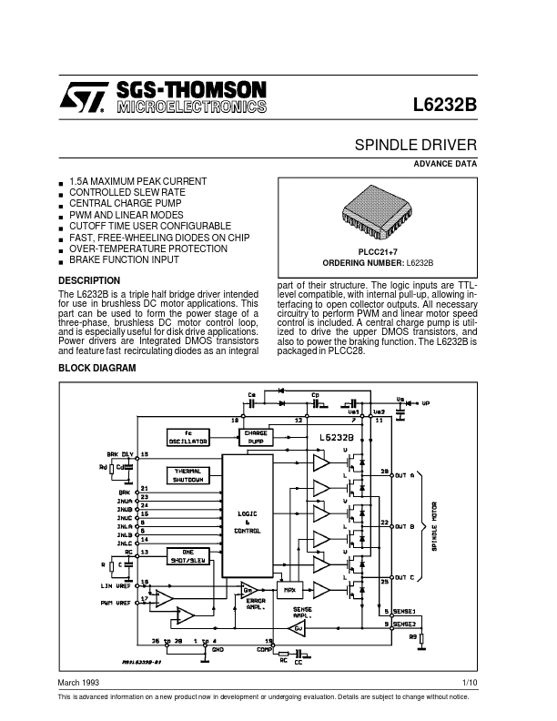
The L6232B is a triple half bridge driver intended for use in brushless DC motor applications. This part can be used to form the power stage of a three-phase, brushless DC motor control loop, and is especially useful for disk drive applications. Power drivers are Integrated DMOS transistors and feature fast recirculating diodes as an integral
BLOCK DIAGRAM
SPINDLE DRIVER
ADVANCE DATA
PLCC21+7 ORDERING NUMBER: L6232B part of their structure. The logic inputs are TTLlevel patible, with internal pull-up, allowing interfacing to open collector outputs. All necessary circuitry to perform PWM and linear motor speed control is included. A central charge pump is utilized to drive the upper DMOS transistors, and also to power the braking function. The L6232B is packaged in PLCC28.
March 1993
1/10
This is advanced information on a new product now in development or undergoing evaluation. Details are subject to change without notice.
PIN DESCRIPTION
Pin 1 to 4 5, 9
6 7, 11
8 10 12 13
Name GND SENSE INLB
VS INLA
CS CP RC
14 15 16 17 18 19 20 21 22 23 24 25 26 to 28
INLC BRK DLY
INUC PWM Vref LIN Vref
P OUTA BRK OUTB INUA INUB OUTC GND
Function mon Ground. Also provides heat-sink to PCB. Output for current sense resistors. Logic Input to turn on the lower driver (Active High). Supply Voltage. Logic input to turn on the lowey driver (Active High). External Charge Pump Capacitor. External Main Charge Pump capacitor. Cutoff Time RC Network in PWM mode. The Resistor value is also used to define the slew-rate in linear mode (LIN). Logic input to turn on the lower driver (Active High). External RC network for the brake delay. Logic Input to turn on the upper driver (Active Low). Input for Reference Control in PWM mode Input for Reference...