Datasheet4U Logo Datasheet4U.com

STPS40L40CW Datasheet (STPS40L40CT/CW) LOW DROP POWER SCHOTTKY RECTIFIER

Manufacturer: STMicroelectronics

Download the STPS40L40CW datasheet PDF. This datasheet also includes the STPS40L40CT variant, as both parts are published together in a single manufacturer document.

📥 Download Datasheet

Note: The manufacturer provides a single datasheet file (STPS40L40CT_STMicroelectronics.pdf) that lists specifications for multiple related part numbers.

General Description

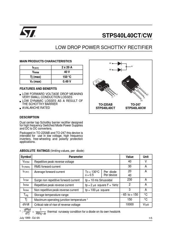
Dual center tap Schottky barrier rectifier designed for high frequency Switched Mode Power Supplies and DC to DC converters.

Packaged in TO-220AB and TO-247 this device is intended for use in low voltage, high frequency inverters, free-wheeling and polarity protection applications.

ABSOLUTE RATINGS (limiting values, per diode) Symbol VRRM IF(RMS) IF(AV) IFSM IRRM IRSM Tstg Tj dV/dt * : RMS forward current Average forward current Surge non repetitive forward current Repetitive peak reverse current Non repetitive peak reverse current Storage temperature range Maximum operating junction temperature * Critical rate of rise of reverse voltage Tc = 130°C δ = 0.5 Parameter Repetitive peak reverse voltage 2 x 20 A A1 K A2 40 V 150 °C 0.49 V A1 K A2 A2 K A1 TO-220AB STPS40L40CT TO-247 STPS40L40CW Value 40 30 Per diode Per device 20 40 230 2 3 - 65 to + 150 150 10000 Unit V A A A A A °C °C V/µs tp = 10 ms Sinusoidal tp = 2 µs square F = 1kHz tp = 100 µs square dPtot 1 < thermal runaway condition for a diode on its own heatsink Rth(j−a) dTj 1/5 July 1999 - Ed: 6A STPS40L40CT/CW THERMAL RESISTANCES Symbol Rth (j-c) Rth(c) Junction to case Parameter Per diode Total Coupling Value 1.5 0.8 0.1 Unit °C/W °C/W When the diodes 1 and 2 are used simultaneously : ∆ Tj(diode 1) = P(diode1) x Rth(j-c)(Per diode) + P(diode 2) x Rth(c) STATIC ELECTRICAL CHARACTERISTICS (per diode) Symbol IR * Parameter Reverse leakage current Forward voltage drop Tests Conditions Tj = 25°C Tj = 100°C Tj = 25°C Tj = 125°C Tj = 25°C Tj = 125°C Pulse test : * tp = 380 µs, δ < 2% To evaluate the conduction losses use the following equation : P = 0.28 x IF(AV) + 0.0105 IF2(RMS) IF = 20 A IF = 20 A IF = 40 A IF = 40 A 0.6 0

Overview

® STPS40L40CT/CW LOW DROP POWER SCHOTTKY RECTIFIER MAIN PRODUCTS CHARACTERISTICS IF(AV) VRRM Tj (max) VF.

Key Features

  • LOW.