Datasheet4U Logo Datasheet4U.com

STPS60L45CW Datasheet LOW DROP POWER SCHOTTKY RECTIFIER

Manufacturer: STMicroelectronics

General Description

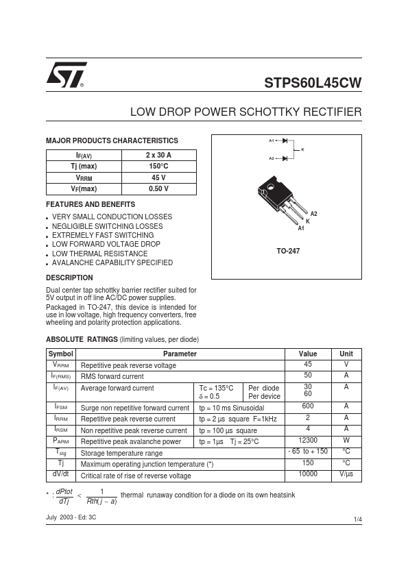
Dual center tap schottky barrier rectifier suited for 5V output in off line AC/DC power supplies.

Packaged in TO-247, this device is intended for use in low voltage, high frequency converters, free wheeling and polarity protection applications.

A1 K A2 A2 K A1 TO-247 ABSOLUTE RATINGS (limiting values, per diode) Symbol VRRM IF(RMS) IF(AV) IFSM IRRM IRSM PARM Tstg Tj dV/dt Parameter Repetitive peak reverse voltage RMS forward current Average forward current Tc = 135°C δ = 0.5 Per diode Per device Surge non repetitive forward current tp = 10 ms Sinusoidal Repetitive peak reverse current tp = 2 µs square F=1kHz Non repetitive peak reverse current tp = 100 µs square Repetitive peak avalanche power tp = 1µs Tj = 25°C Storage temperature range Maximum operating junction temperature (*) Critical rate of rise of reverse voltage Value 45 50 30 60 600 2 4 12300 - 65 to + 150 150 10000 * : dPtot < 1 thermal runaway condition for a diode on its own heatsink dTj Rth( j − a) Unit V A A A A A W °C °C V/µs July 2003 - Ed: 3C 1/4 STPS60L45CW THERMAL RESISTANCES Symbol Rth (j-c) Junction to case Rth (c) Parameter Per diode Total Coupling Value 0.75 0.42 0.1 Unit °C/W °C/W When the diodes 1 and 2 are used simultaneously : ∆ Tj(diode 1) = P(diode1) x Rth(j-c)(Per diode) + P(diode 2) x Rth(c) STATIC ELECTRICAL CHARACTERISTICS (per diode) Symbol IR * VF * Parameter Reverse leakage current Forward voltage drop Pulse test : * tp = 380 µs, δ < 2% Tests Conditions Tj = 25°C VR = 45 V Tj = 125°C Tj = 25°C IF = 30 A Tj = 125°C IF = 30 A Tj = 25°C IF = 60 A Tj = 125°C IF = 60 A Min.

Overview

® STPS60L45CW LOW DROP POWER SCHOTTKY RECTIFIER MAJOR PRODUCTS CHARACTERISTICS IF(AV) Tj (max) VRRM VF(max) 2 x 30 A 150°C 45 V 0.

Key Features

  • s VERY SMALL.