TTC3710B
TTC3710B is NPN Transistor manufactured by Toshiba.
Bipolar Transistors Silicon NPN Epitaxial Type
1. Applications
- High-Current Switching
2. Features
(1) Low collector-emitter saturation voltage: VCE(sat) = 0.4 V (max) (IC = 6 A , IB = 0.3 A) (2) High speed switching: tstg = 1 µs (typ.) (3) plementary to TTA1452B
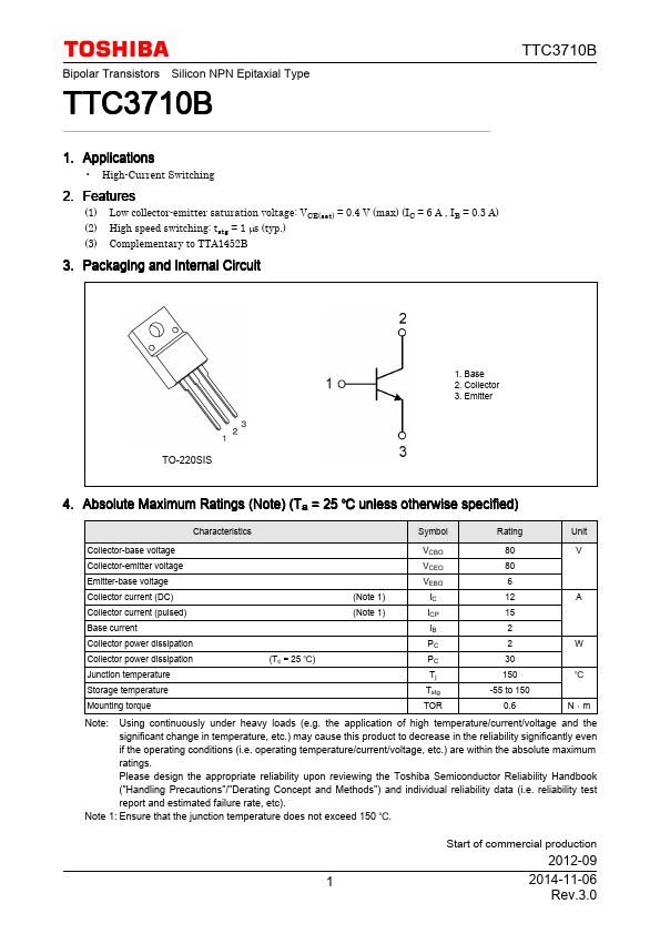
3. Packaging and Internal Circuit
1. Base 2. Collector 3. Emitter
TO-220SIS
4....