Datasheet4U Logo Datasheet4U.com

TA8411L - STEPPING MOTOR SYSTEM DRIVER

Description

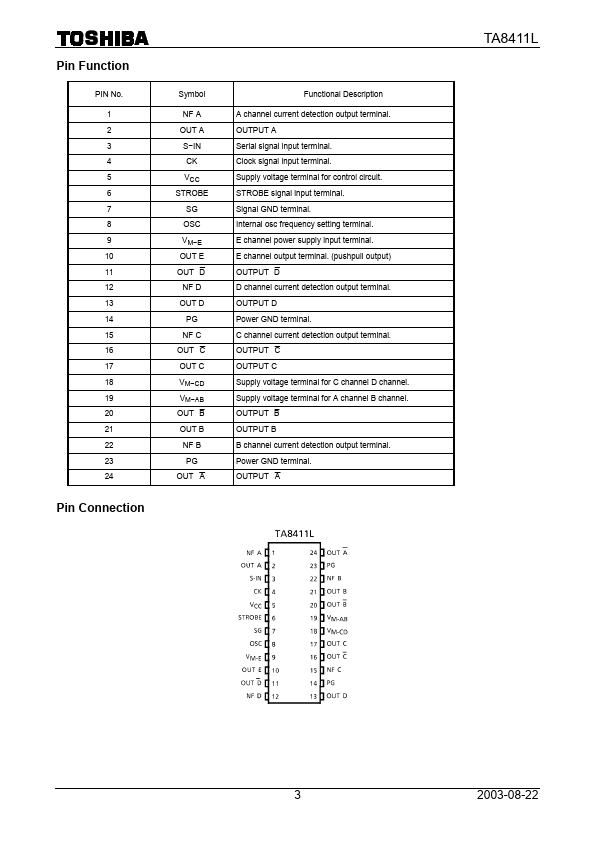
A channel current detection output terminal.

OUTPUT A Serial signal input terminal.

Clock signal input terminal.

Features

  • CMOS-compatible input level (built-in pull-down resistor) Two built-in biphase, bipolar stepping motor drivers (bipolar driving and chopper type) Built-in push-pull driver Built-in register reset circuit Operating output voltage range: VM = 0 to 27 V Operating supply voltage range: VCC = 4.5 to 5.5 V TA8411L 1 2003-08-22 Block Diagram TA8411L Note 1: Capacitance connect to each Power Supply Terminal is required to change to optimum value for noise elimination and also required to connect di.

📥 Download Datasheet

Datasheet preview – TA8411L
Other Datasheets by Toshiba Semiconductor

Full PDF Text Transcription

Click to expand full text
TOSHIBA Bipolar Linear Integrated Circuit Silicon Monolithic TA8411L Biphase Bipolar Stepper and Push-Pull Driver The TA8411L incorporates drivers for bipolar stepping motors (chopper type) and a DC motor driver. Its input section is a serial input type and has a shift register with a 12-bit latch. Its output section has a push-pull driver that can supply up to 0.6 A and two sets of 8 bipolar drivers that can supply up to 0.8 A. It can control two bipolar stepping motors and one brushed motor or solenoid. The VM-AB, VM-CD, VM-E and VCC power supply voltages are independent of one another, and they can have any voltage relationship among them. Because the output section incorporates a circuit that can switch at high speed, it can support a PWM frequency of up to 200 kHz. Weight: 4.
Published: |