Datasheet4U Logo Datasheet4U.com

TA8415P - STEPPING MOTOR CONTROLLER/DRIVER

Description

Direction Control Input Function Table A Phase Excitation Mode Input Truth Table B Phase Control Input MO = “L” at Initial State φ1 Output φ2 Output GND φ3 Output φ4 Output Outputs are Enable at E = “H” Clock Output Clock Input 1 Clock Input 2 Truth Table A Reset Input VCC TRUTH TAB

Features

  • l 1 chip stepping motor controller / driver. l 3 or 4 phase and 1, 1.
  • 2, 2 phase excitation drive are available. l CW / CCW rotation and 1 clock or 2 clock drive are available. l Hysteresis is provided with clock, CW / CCW, reset inputs for noise protection. l Output enable, initial detect are available. l Output current up to 400mA (MAX. ) BLOCK.

📥 Download Datasheet

Datasheet preview – TA8415P
Other Datasheets by Toshiba Semiconductor

Full PDF Text Transcription

Click to expand full text
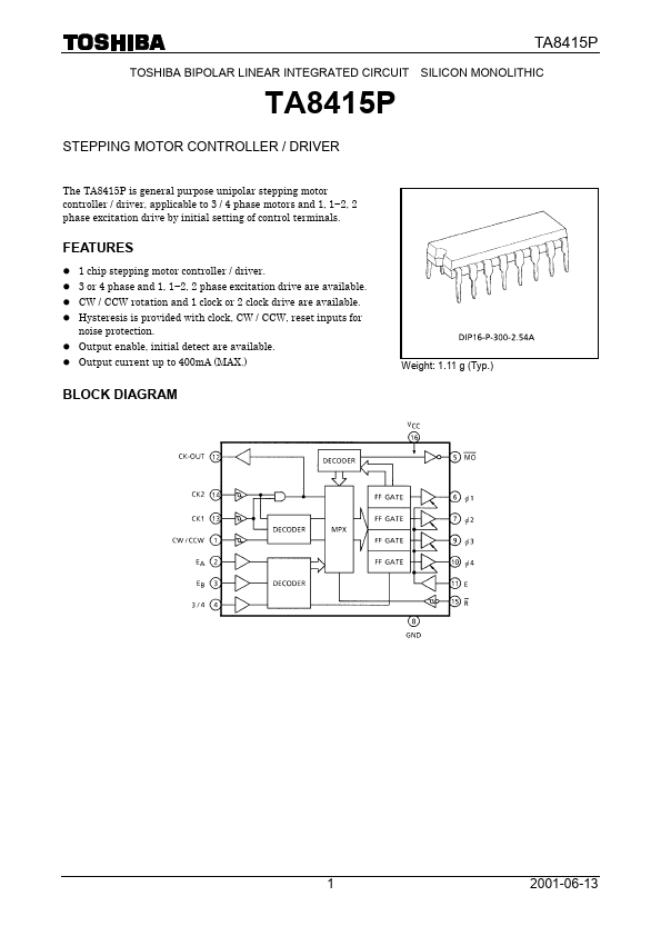
TA8415P TOSHIBA BIPOLAR LINEAR INTEGRATED CIRCUIT SILICON MONOLITHIC TA8415P STEPPING MOTOR CONTROLLER / DRIVER The TA8415P is general purpose unipolar stepping motor controller / driver, applicable to 3 / 4 phase motors and 1, 1−2, 2 phase excitation drive by initial setting of control terminals. FEATURES l 1 chip stepping motor controller / driver. l 3 or 4 phase and 1, 1−2, 2 phase excitation drive are available. l CW / CCW rotation and 1 clock or 2 clock drive are available. l Hysteresis is provided with clock, CW / CCW, reset inputs for noise protection. l Output enable, initial detect are available. l Output current up to 400mA (MAX.) BLOCK DIAGRAM Weight: 1.11 g (Typ.) 1 2001-06-13 PIN FUNCTION TA8415P PIN No.
Published: |