DG612E Overview
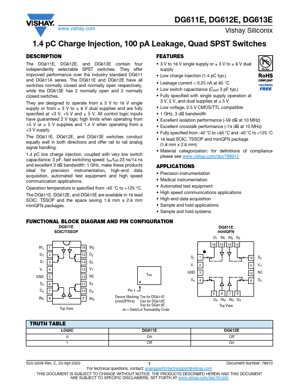
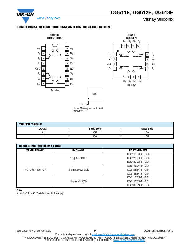
The DG611E, DG612E, and DG613E contain four independently selectable SPST switches. They offer improved performance over the industry standard DG611 and DG611A series. The DG611E and DG612E have all switches normally closed and normally open respectively, while the DG613E has 2 normally open and 2 normally closed switches.
DG612E Key Features
- 3 V to 16 V single supply or ± 3 V to ± 8 V dual supply
- Low charge injection (1.4 pC typ.)
- Leakage current < 0.25 nA at 85 °C
- Low switch capacitance (Csoff 3 pF typ.)
- Fully specified with single supply operation at
- Low voltage, 2.5 V CMOS/TTL patible
- 1 GHz, 3 dB bandwidth
- Excellent isolation performance (-59 dB at 10 MHz)
- Excellent crosstalk performance (-74 dB at 10 MHz)
- Fully specified from -40 °C to +85 °C and -40 °C to +125 °C
DG612E Applications
- 3 V to 16 V single supply or ± 3 V to ± 8 V dual supply