www.vishay.com
VS-CPV363M4FPbF
Vishay Semiconductors
IGBT SIP Module
(Fast IGBT)
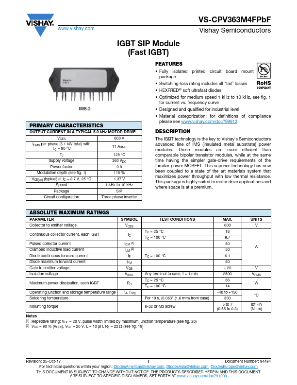
IMS-2
PRIMARY CHARACTERISTICS
OUTPUT CURRENT IN A TYPICAL 5.0 kHz MOTOR DRIVE
VCES
IRMS per phase (3.1 kW total) with
TC = 90 °C
TJ
Supply voltage
Power factor
600 V
11 ARMS
125 °C
360 VDC
0.8
Modulation depth (see fig. 1)
115 %
VCE(on) (typical) at IC = 8.7 A, 25 °C
Speed
1.37 V
1 kHz to 10 kHz
Package
SIP
Circuit configuration
Three phase inverter
FEATURES
• Fully isolated printed circuit board mount
package
• Switching-loss rating includes all “tail” losses
• HEXFRED® soft ultrafast diodes
• Optimized for medium speed 1 kHz to 10 kHz, see fig. 1
for current vs. frequency curve
• Designed and qualified for industrial level
• Material categorization: for definitions of compliance
please see www.vishay.com/doc?99912
DESCRIPTION
The IGBT technology is the key to Vishay’s Semiconductors
advanced line of IMS (insulated metal substrate) power
modules. These modules are more efficient than
comparable bipolar transistor modules, while at the same
time having the simpler gate-drive requirements of the
familiar power MOSFET. This superior technology has now
been coupled to a state of the art materials system that
maximizes power throughput with low thermal resistance.
This package is highly suited to motor drive applications and
where space is at a premium.
ABSOLUTE MAXIMUM RATINGS
PARAMETER
Collector to emitter voltage
SYMBOL
VCES
Continuous collector current, each IGBT
IC
Pulsed collector current
Clamped inductive load current
Diode continuous forward current
Diode maximum forward current
Gate to emitter voltage
Isolation voltage
ICM (1)
ILM (2)
IF
IFM
VGE
VISOL
Maximum power dissipation, each IGBT
PD
Operating junction and storage temperature range
Soldering temperature
TJ, TStg
Mounting torque
TEST CONDITIONS
TC = 25 °C
TC = 100 °C
TC = 100 °C
Any terminal to case, t = 1 min
TC = 25 °C
TC = 100 °C
For 10 s, (0.063" (1.6 mm) from case)
6-32 or M3 screw
Notes
(1) Repetitive rating; VGE = 20 V, pulse width limited by maximum junction temperature (see fig. 20)
(2) VCC = 80 % (VCES), VGE = 20 V, L = 10 μH, Rg = 22 (see fig. 19)
MAX.
600
16
8.7
50
50
6.1
50
± 20
2500
36
14
-40 to +150
300
5 to 7
(0.55 to 0.8)
UNITS
V
A
V
VRMS
W
°C
lbf in
(N m)
Revision: 25-Oct-17
1
Document Number: 94484
For technical questions within your region: DiodesAmericas@vishay.com, DiodesAsia@vishay.com, DiodesEurope@vishay.com
THIS DOCUMENT IS SUBJECT TO CHANGE WITHOUT NOTICE. THE PRODUCTS DESCRIBED HEREIN AND THIS DOCUMENT
ARE SUBJECT TO SPECIFIC DISCLAIMERS, SET FORTH AT www.vishay.com/doc?91000