TPS92643-Q1
TPS92643-Q1 is Automotive 3-A Synchronous Buck LED Driver manufactured by Texas Instruments.
Features
- AEC-Q100 qualified for automotive applications
- Grade 1:
- 40°C to 125°C ambient operating temperature
- Device HBM classification level H1C
- Device CDM classification level C5
- Input voltage range: 5.5 V to 36 V
- Operation down to 5.15 V after start-up
- Up to 3-A continuous with 4% accuracy
- Adaptive on-time current control
- Low offset high-side current sense amplifier
- Stable with any bination of ceramic, and aluminum capacitors
- Programmable switching frequency from 100 k Hz to 2.2 MHz
- Advanced dimming operation
- 1000:1 precision PWM dimming
- 15:1 precision analog dimming
- 1.4-k Hz internal analog input to PWM duty cycle translation
- Cycle-by-cycle switch overcurrent protection
- Open-drain fault indicator output
- LED short circuit, open circuit and cable harness fault indication
- Thermal shutdown protection
2 Applications
- Headlight
- Front fog light LED driver module
3 Description
The TPS92643-Q1 is a monolithic, synchronous Buck LED driver with a wide 5.5-V to 36-V operating input voltage range and 40-V tolerance that supports load dump for duration of 400 ms. The TPS92643Q1 implements an adaptive on-time average current mode control based on inductor valley current detection. The adaptive on-time control provides near constant switching frequency that can be set between 100 k Hz and 2.2 MHz. Inductor current sensing and closed-loop feedback enables better than ±4% accuracy over wide input, output and ambient temperature.
The high-performance LED driver can independently modulate LED current using both analog or PWM dimming techniques. Linear analog dimming range with over 15:1 range is obtained by setting the IADJ voltage. PWM dimming of LED current is achieved by directly modulating the UDIM input pin with desired duty cycle or setting the analog voltage at APWM to enable internal analog-to-PWM conversion. The internal PWM generator translates the external analog voltage by paring it to an internal 1.4-k Hz ramp signal.
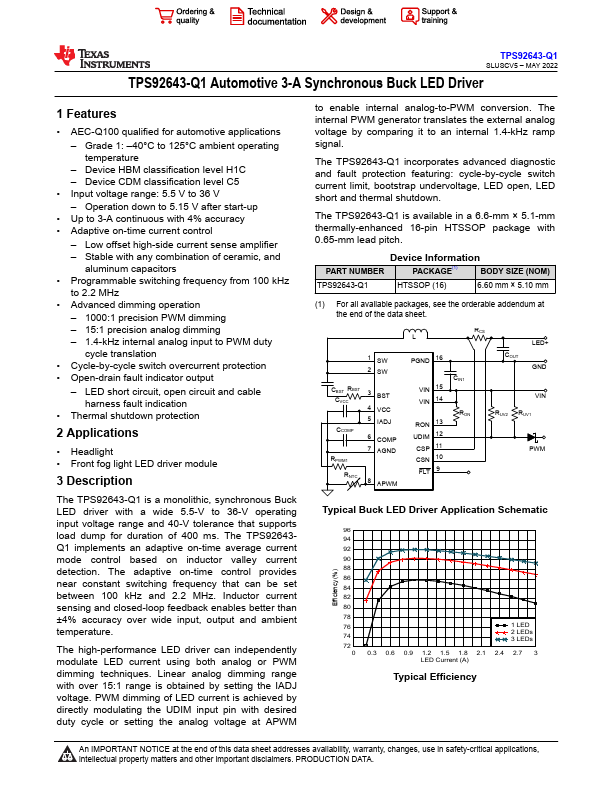
The...