Click to expand full text
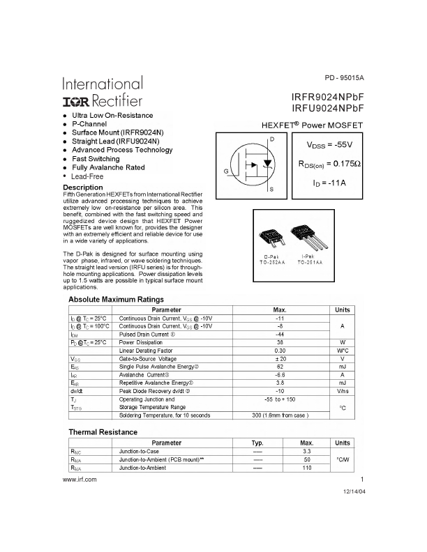
• Lead-Free
PD - 95015A
IRFR9024NPbF IRFU9024NPbF
www.irf.com
1 12/14/04
IRFR/U9024NPbF
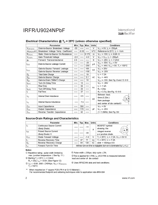
2
www.irf.com
IRFR/U9024NPbF
www.irf.com
3
IRFR/U9024NPbF
4
www.irf.com
IRFR/U9024NPbF
www.irf.com
5
IRFR/U9024NPbF
6
www.irf.com
IRFR/U9024NPbF
Peak Diode Recovery dv/dt Test Circuit
+
Circuit Layout Considerations
• Low Stray Inductance
• Ground Plane
• Low Leakage Inductance
Current Transformer
-
+
-
-
+
• dv/dt controlled by RG
+
• ISD controlled by Duty Factor "D" • D.U.T. - Device Under Test
-
* Reverse Polarity for P-Channel
** Use P-Channel Driver for P-Channel Measurements
Driver Gate Drive
P.W.
Period
D=
P.W. Period
VGS=10V
D.U.T. ISD Waveform
Reverse Recovery Current
Body Diode Forward
Current di/dt
D.U.T.
 IRFR9024N Datasheet