Datasheet4U Logo Datasheet4U.com

NJW1340 Datasheet - JRC

Video Switch / SSOP32

NJW1340 Features

* q Operating Voltage 4.5 to 5.5V 2 q I C BUS Interface q 5-input 1-output video switch q 3-input 1-output 2-circuit video switch q 6th order Low Pass Filter q Internal synchronous separation circuit q Internal synchronous signal detection circuit q Power Save Circuit q Bi-CMOS Technology q Package Ou

NJW1340 General Description

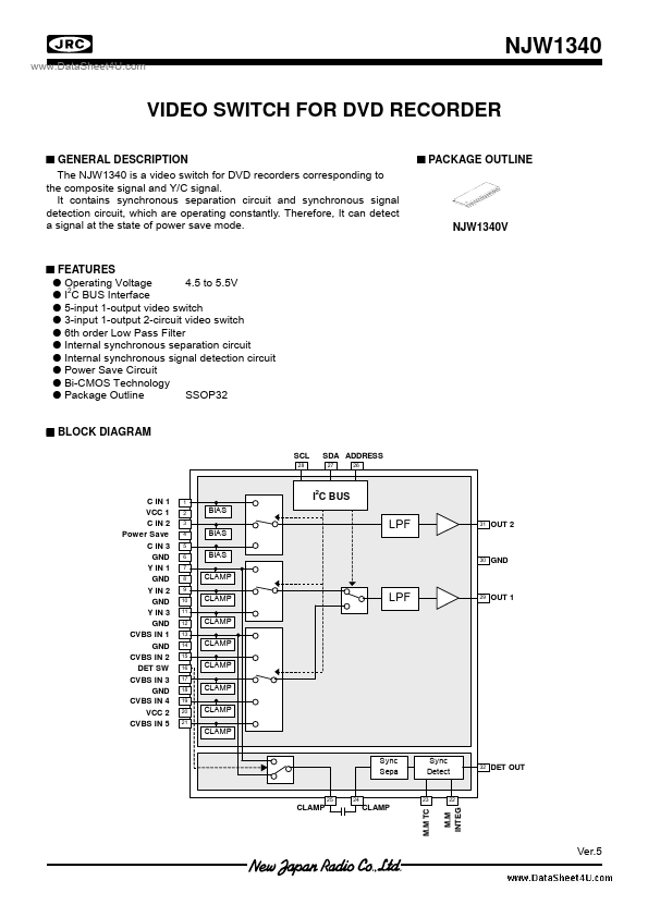
The NJW1340 is a video switch for DVD recorders corresponding to the composite signal and Y/C signal. It contains synchronous separation circuit and synchronous signal detection circuit, which are operating constantly. Therefore, It can detect a signal at the state of power save mode. s PACKAGE OUTL.

NJW1340 Datasheet (209.25 KB)

Preview of NJW1340 PDF

Datasheet Details

Part number:

NJW1340

Manufacturer:

JRC

File Size:

209.25 KB

Description:

Video switch / ssop32.

📁 Related Datasheet

NJW1341 8input-2output Video Driver (NJR)

NJW1341VC3 8input-2output Video Driver (NJR)

NJW1342 4in-2out Video Driver (New Japan Radio)

NJW1300A SIGNAL PROCESSOR (New Japan Radio)

NJW1300B Signal Processor for TFT Display / QFP64-G1 (JRC)

NJW1301 Signal Processor for TFT Display / QFP64-K1 (JRC)

NJW1302G NPN-PNP Silicon Power Bipolar Transistors (ON Semiconductor)

NJW1302G PNP Transistor (INCHANGE)

NJW1303 Synchronous Signal Separator and Detector / SSOP14 (JRC)

NJW1320 Video Switch / QFP48-P1 (JRC)

TAGS

NJW1340 Video Switch SSOP32 JRC

Image Gallery

NJW1340 Datasheet Preview Page 2 NJW1340 Datasheet Preview Page 3

NJW1340 Distributor