Click to expand full text
CERAMIC CHIP CAPACITORS
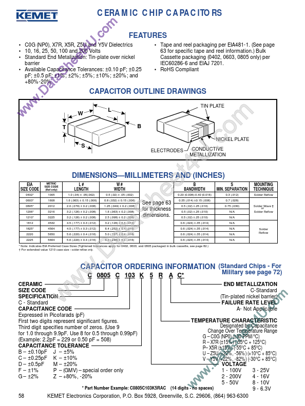
m o FEATURES c . • C0G (NP0), X7R, X5R, Z5U and • Tape and reel packaging per EIA481-1. (See page UY5V Dielectrics 4 • 10, 16, 25, 50, 100 and 200 Volts 63 for specific tape and reel information.) Bulk t • Standard End Metalization: Tin-plate over nickel Cassette packaging (0402, 0603, 0805 only) per e e barrier IEC60286-6 and EIAJ 7201. h • Available Capacitance Tolerances: ±0.10 pF; ±0.25 • RoHS Compliant S±2%; ±5%; ±10%; ±20%; and pF; ±0.5 pF; ±1%; +80%-20% ta a CAPACITOR OUTLINE DRAWINGS D . w w L W w
TIN PLATE
T S
B
ELECTRODES
CONDUCTIVE METALLIZATION
DIMENSIONS—MILLIMETERS AND (INCHES)
EIA SIZE CODE
0402* 0603* 0805* 1206* 1210* 1812 1825* 2220 2225 METRIC SIZE CODE (Ref only) 1005 1608 2012 3216 3225 4532 4564 5650 5664
L# LENGTH
1.0 (.04) ± .05(.
 C0603C104K3 Datasheet