FDB107 Overview
| Part | FDB107 |
|---|---|
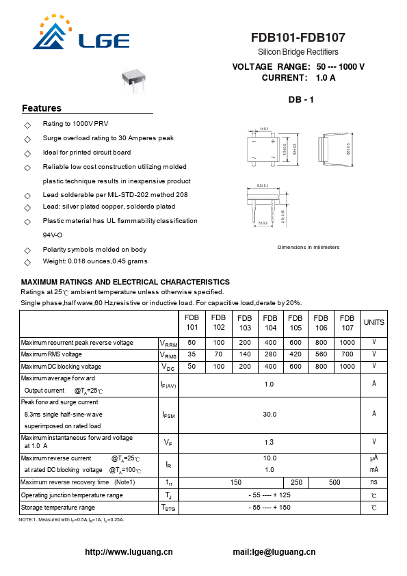
| Description | Silicon Bridge Rectifiers |
| Manufacturer | LGE |
| Size | 146.11 KB |
| Seller | Inventory | Price Breaks | Buy |
|---|---|---|---|
| MRO Supply | -2 | 1+ : 227.77 USD | View Offer |
| Walker Industrial | -4 | 1+ : 303.7 USD | View Offer |
| Part Number | Manufacturer | Description |
|---|---|---|
| FDB107S | SeCoS Halbleitertechnologie GmbH | 1.0 Amp Silicon Bridge Rectifiers |
| FDB10AN06A0 | Fairchild Semiconductor | N-Channel MOSFET |
| FDB103S | SeCoS Halbleitertechnologie GmbH | 1.0 Amp Silicon Bridge Rectifiers |
| FDB104S | SeCoS Halbleitertechnologie GmbH | 1.0 Amp Silicon Bridge Rectifiers |
| FDB105S | SeCoS Halbleitertechnologie GmbH | 1.0 Amp Silicon Bridge Rectifiers |