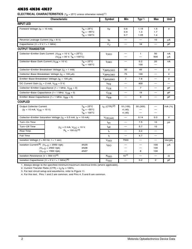
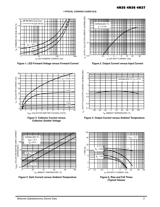
4N35 Datasheet Text
MOTOROLA
SEMICONDUCTOR TECHNICAL DATA
Order this document by 4N35/D
GlobalOptoisolator™
6-Pin DIP Optoisolators Transistor Output
The 4N35, 4N36 and 4N37 devices consist of a gallium arsenide infrared emitting diode optically coupled to a monolithic silicon phototransistor detector.
- Current Transfer Ratio
- 100% Minimum @ Specified Conditions
- Guaranteed Switching Speeds
- Meets or Exceeds all JEDEC Registered Specifications
- To order devices that are tested and marked per VDE 0884 requirements, the suffix ”V” must be included at end of part number. VDE 0884 is a test option. Applications
- General Purpose Switching Circuits
- Interfacing and coupling systems of different potentials and impedances
- Regulation Feedback Circuits
- Monitor & Detection Circuits
- Solid State Relays MAXIMUM RATINGS (TA = 25°C unless otherwise noted)
Rating INPUT LED Reverse Voltage Forward Current
- Continuous LED Power Dissipation @ TA = 25°C with Negligible Power in Output Detector Derate above 25°C OUTPUT TRANSISTOR Collector- Emitter Voltage Emitter- Base Voltage Collector- Base Voltage Collector Current
- Continuous Detector Power Dissipation @ TA = 25°C with Negligible Power in Input LED Derate above 25°C TOTAL DEVICE Isolation Source Voltage(1) (Peak ac Voltage, 60 Hz, 1 sec Duration) Total Device Power Dissipation @ TA = 25°C Derate above 25°C Ambient Operating Temperature Range(2) Storage Temperature Range(2) Soldering Temperature (10 sec, 1/16″ from case) VISO PD TA Tstg TL 7500 250 2.94
- 55 to +100
- 55 to +150 260 Vac(pk) mW mW/°C °C °C °C VCEO VEBO VCBO IC PD 30 7 70 150 150 1.76 Volts Volts Volts mA mW mW/°C VR IF PD 6 60 120 1.41 Volts mA mW mW/°C 2 3 Symbol Value Unit 1
[CTR = 100% Min]
4N35
- 4N36 4N37
- Motorola Preferred Device
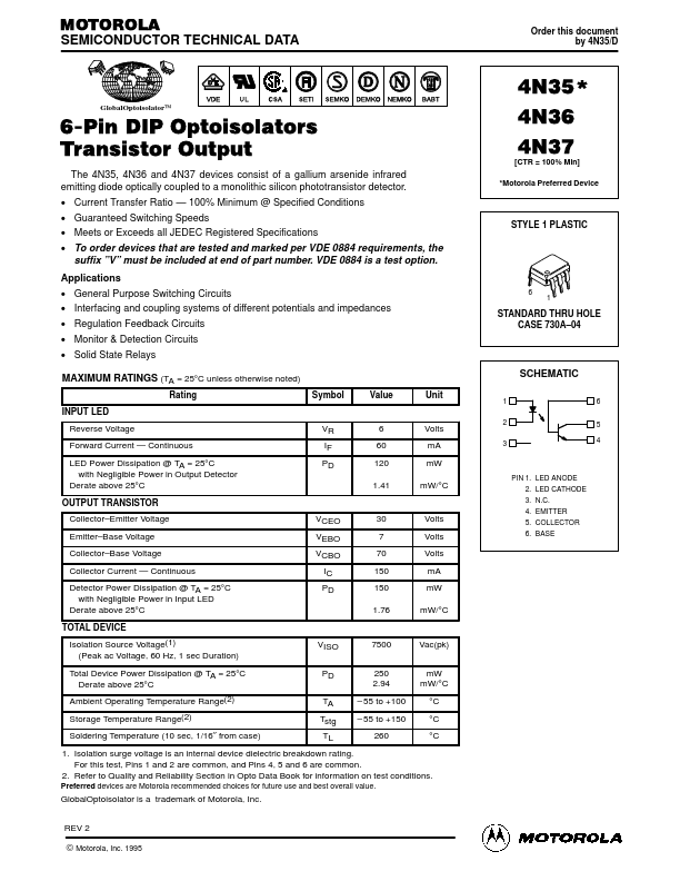
STYLE 1 PLASTIC
6
1
STANDARD...