Datasheet4U Logo Datasheet4U.com

UAA1041B - AUTOMOTIVE DIRECTION INDICATOR

Datasheet Summary

Description

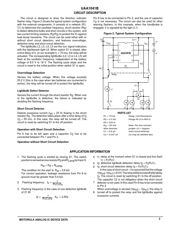
The circuit is designed to drive the direction indicator flasher relay.

Figure 2 shows the typical system configuration with the external components.

Features

  • overvoltage, defective lamp and short circuit detection. The lightbulbs L2, L3, L4, L5 are the turn signal indicators with the dashboard.
  • light L6. When switch S1 is closed, after a time delay of t1 (in our example t1 = 75 ms), the relay will be actuated. The corresponding lightbulbs (L2, L3 or L4, L5) will flash at the oscillator frequency, independent of the battery voltage of 8.0 V to 18 V. The flashing cycle stops and the circuit is reset to the initial position when switch S1 is open.

📥 Download Datasheet

Datasheet preview – UAA1041B

Datasheet Details

Part number UAA1041B
Manufacturer Motorola
File Size 92.25 KB
Description AUTOMOTIVE DIRECTION INDICATOR
Datasheet download datasheet UAA1041B Datasheet
Additional preview pages of the UAA1041B datasheet.
Other Datasheets by Motorola

Full PDF Text Transcription

Click to expand full text
Order this document by UAA1041B/D UAA1041B Automotive Direction Indicator This device was designed for use in conjunction with a relay in automotive applications. It is also applicable for other warning lamps such as “handbrake ON,” etc. AUTOMOTIVE DIRECTION INDICATOR SEMICONDUCTOR TECHNICAL DATA • • • • • Defective Lamp Detection Overvoltage Protection Short Circuit Detection and Relay Shutdown to Prevent Risk of Fire Reverse Battery Connection Protection Integrated Suppression Clamp Diode 8 1 NO SUFFIX PLASTIC PACKAGE CASE 626 Figure 1.
Published: |