UPD16803 Overview
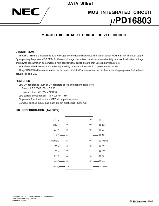
The µPD16803 is a monolithic dual H bridge driver circuit which uses N-channel power MOS FETs in its driver stage. By employing the power MOS FETs for the output stage, this driver circuit has a substantially improved saturation voltage and power consumption as pared with conventional driver circuits that use bipolar transistors. In addition, the drive current can be adjusted by an external resistor in a...
UPD16803 Key Features
- Low ON resistance (sum of ON resistors of top and bottom transistors) RON1 = 1.5 Ω TYP. (VM = 5.0 V) RON2 = 2.0 Ω TYP. (
- Low current consumption: IDD = 0.4 mA TYP
- Stop mode function that turns OFF all output transistors
- pact surface mount package: 20-pin plastic SOP (300 mil)