Datasheet Details
| Part number | UM10512 |
|---|---|
| Manufacturer | NXP Semiconductors |
| File Size | 1.26 MB |
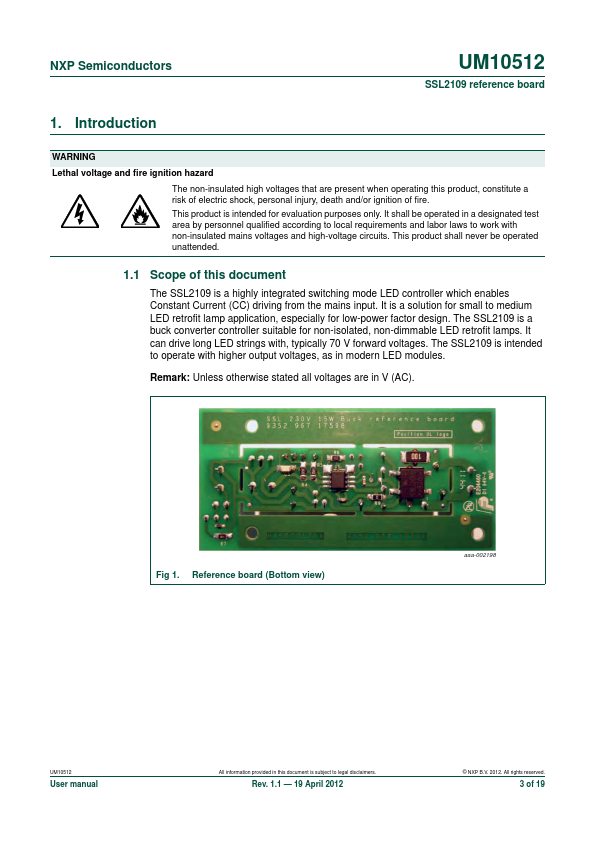
| Description | SSL2109 reference board |
| Datasheet |
 UM10512 Datasheet UM10512 Datasheet
|
|
|
All information provided in this document is subject to legal disclaimers.
© NXP B.V.
2012.
19 April 2012 2 of 19 datasheet pdf - http://www.DataSheet4U.net/ NXP Semiconductors
| Part number | UM10512 |
|---|---|
| Manufacturer | NXP Semiconductors |
| File Size | 1.26 MB |
| Description | SSL2109 reference board |
| Datasheet |
UM10512 Datasheet
|
|
|
|