NCP1382
NCP1382 is Low Standby High Performance PWM Controller manufactured by onsemi.
- Part of the NCP1381 comparator family.
- Part of the NCP1381 comparator family.
NCP1381, NCP1382
Low- Standby High Performance PWM Controller
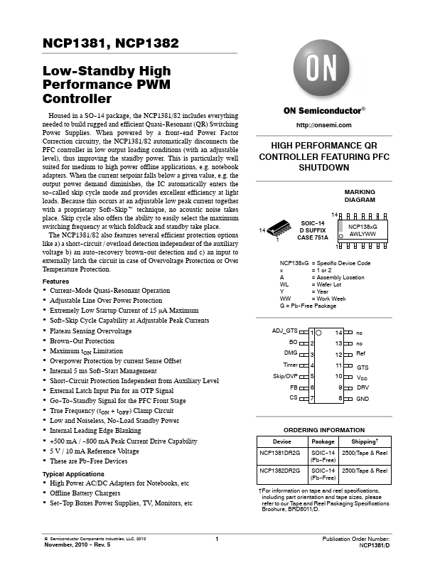
Housed in a SO--14 package, the NCP1381/82 includes everything needed to build rugged and efficient Quasi--Resonant (QR) Switching Power Supplies. When powered by a front--end Power Factor Correction circuitry, the NCP1381/82 automatically disconnects the PFC controller in low output loading conditions (with an adjustable level), thus improving the standby power. This is particularly well suited for medium to high power offline applications, e.g. notebook adapters. When the current setpoint falls below a given value, e.g. the output power demand diminishes, the IC automatically enters the so--called skip cycle mode and provides...