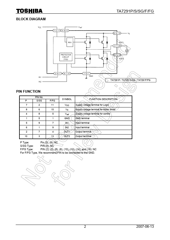
Description
7
2
11
VCC
Supply voltage terminal for Logic
8
6
15
VS
Supply voltage terminal for Motor driver
4
8
5
Vref
Supply voltage terminal for control
1
5
1
GND
GND terminal
5
9
7
IN1
Input terminal
6
1
9
IN2
Input terminal
2
7
4
OUT1 Output terminal
10
3
13
OUT2 Output terminal
P Type:
Pin (3), (9): NC
S/SG Type:
PIN (4): NC
F/FG Type:
PIN (2), (3), (6), (8), (10), (12), (14), and (16): NC
For F/FG Type, We recommend FIN to be connected to the GND.2
2007-
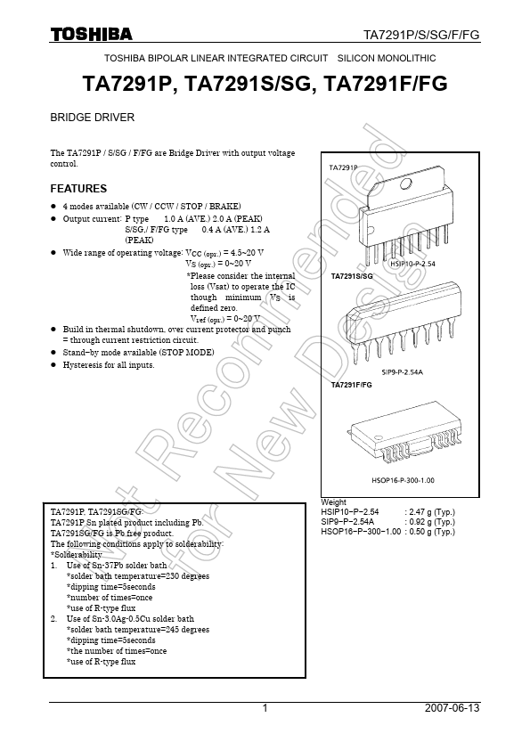
Features
- z 4 modes available (CW / CCW / STOP / BRAKE) z Output current: P type 1.0 A (AVE. ) 2.0 A (PEAK)
S/SG,/ F/FG type 0.4 A (AVE. ) 1.2 A (PEAK) z Wide range of operating voltage: VCC (opr. ) = 4.5~20 V
VS (opr. ) = 0~20 V.
- Please consider the internal loss (Vsat) to operate the IC though minimum VS is defined zero. Vref (opr. ) = 0~20 V z Build in thermal shutdown, over current protector and punch = through current restriction circuit. z Stand.
- by mode available (STOP MODE) z Hysteresis for.
 TA7291F_ToshibaSemiconductor.pdf