Datasheet Details
| Part number | TB6524FN |
|---|---|
| Manufacturer | Toshiba Semiconductor |
| File Size | 224.17 KB |
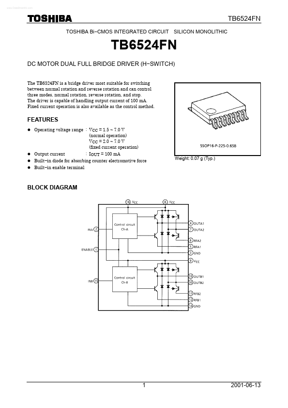
| Description | DC MOTOR DUAL FULL BRIDGE DRIVER |
| Datasheet |
 TB6524FN Datasheet TB6524FN Datasheet
|
|
|
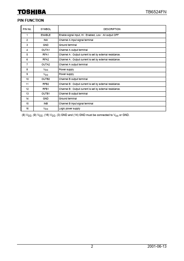
Enable signal input, Hi : Enabled, Low : All output OFF Channel A input signal terminal Ground terminal Channel A output terminal Channel A : Output current is set by external resistance.
Channel A : Output current is set by external resistance.
| Part number | TB6524FN |
|---|---|
| Manufacturer | Toshiba Semiconductor |
| File Size | 224.17 KB |
| Description | DC MOTOR DUAL FULL BRIDGE DRIVER |
| Datasheet |
TB6524FN Datasheet
|
|
|
|