5SHY55L4500
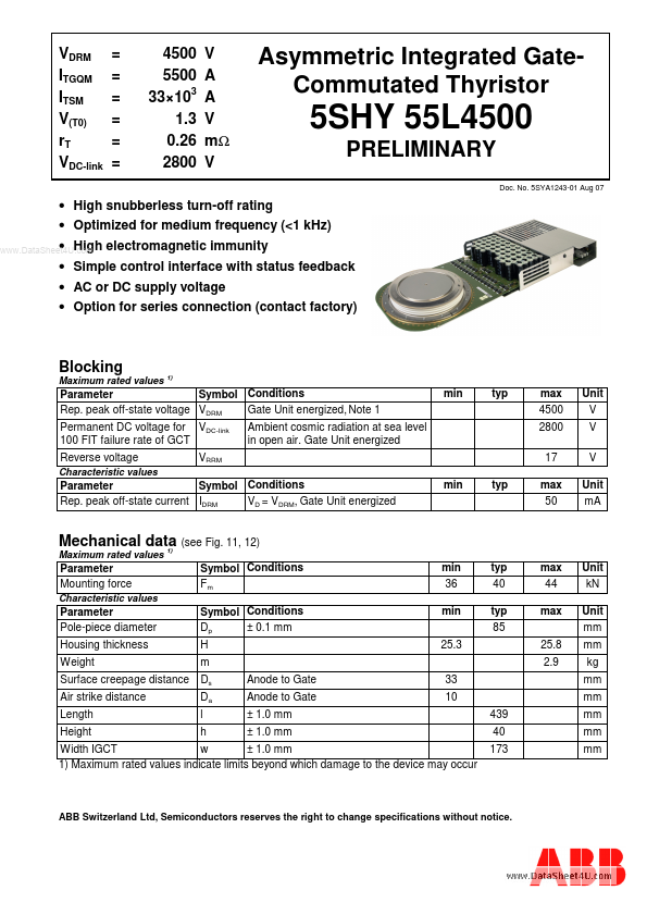
5SHY55L4500 is Asymmetric Integrated Gate- Commutated Thyristor manufactured by ABB.
VDRM ITGQM ITSM V(T0) r T VDC-link
= = = = = =
4500 5500 33×103 1.3 0.26 2800
V A A V mΩ V
Asymmetric Integrated Gatemutated Thyristor
5SHY 55L4500
PRELIMINARY
Doc. No. 5SYA1243-01 Aug 07
- High snubberless turn-off rating
- Optimized for medium frequency (<1 k Hz)
- High .. electromagnetic immunity
- Simple control interface with status feedback
- AC or DC supply voltage
- Option for series connection (contact factory)
Blocking
Maximum rated values
1)
Parameter Symbol Conditions Rep. peak off-state voltage VDRM Gate Unit energized, Note 1 Permanent DC voltage for VDC-link 100 FIT failure rate of GCT Reverse voltage
Characteristic values min typ max 4500 2800 17
Unit V V V Unit m A
Ambient cosmic radiation at sea level in open air. Gate Unit energized
VRRM min typ
Parameter Symbol Conditions Rep. peak off-state current IDRM VD = VDRM, Gate Unit energized max 50
Mechanical data (see Fig. 11, 12) 1)
Maximum rated values
Parameter Mounting force
Characteristic values
Symbol Conditions Fm Symbol Conditions Dp ± 0.1 mm H m Ds Da l h Anode to Gate Anode to Gate ± 1.0 mm ± 1.0 mm min 36 min 25.3 33 10 typ 40 typ 85 max 44 max 25.8 2.9
Unit k N Unit mm mm kg mm mm
Parameter Pole-piece diameter Housing thickness Weight Surface creepage distance Air strike distance Length Height
439 40 173 mm mm mm
Width IGCT w ± 1.0 mm 1) Maximum rated values indicate limits beyond which damage to the device may occur
ABB Switzerland Ltd, Semiconductors reserves the right to change specifications without notice.
5SHY 55L4500
GCT Data
On-state (see Fig.1)3, 4, 5, 6, 14, 15)
Maximum rated values
Parameter Max. average on-state current Max. RMS on-state current Max. peak non-repetitive surge on-state current Limiting load integral Max. peak non-repetitive surge on-state current Limiting load integral
.. Max. peak
Symbol Conditions IT(AV)M Half sine wave, TC = 85 °C, Double side cooled IT(RMS) ITSM I2t ITSM I2t ITSM I2t LD di T/dtcr Only relevant for applications...