UT54ACS109
UT54ACS109 is Radiation-Hardened Dual J-K Flip-Flops manufactured by Aeroflex Circuit Technology.
FEATURES
- -
- -
- - radiation-hardened CMOS
- Latchup immune High speed Low power consumption Single 5 volt supply Available QML Q or V processes Flexible package
- 16-pin DIP
- 16-lead flatpack
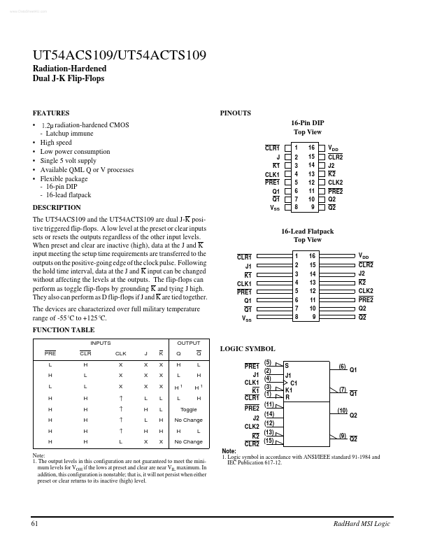
PINOUTS 16-Pin DIP Top View
CLR1 J K1 CLK1 PRE1 Q1 Q1 VSS 1 2 3 4 5 6 7 8 16 15 14 13 12 11 10 9 VDD CLR2 J2 K2 CLK2 PRE2 Q2 Q2
DESCRIPTION
The UT54ACS109 and the UT54ACTS109 are dual J-K positive triggered flip-flops. A low level at the preset or clear inputs sets or resets the outputs regardless of the other input levels. When preset and clear are inactive (high), data at the J and K input meeting the setup time requirements are transferred to the outputs on the positive-going edge of the clock pulse. Following the hold time interval, data at the J and K input can be changed without affecting the levels at the outputs. The flip-flops can perform as toggle flip-flops by grounding K and tying J high. They also can perform as D flip-flops if J and K are tied together. The devices are characterized over full military temperature range of -55 C to +125 C. FUNCTION TABLE
INPUTS PRE L H L H H H H H CLR H L L H H H H H L CLK X X X J X X X L H L H X K X X X L L H H X OUTPUT Q H L H1 L Q L H H1 H Toggle No Change H L
16-Lead Flatpack Top View
CLR1 J1 K1 CLK1 PRE1 Q1 Q1 VSS 1 2 3 4 5 6 7 8 16 15 14 13 12 11 10 9 VDD CLR2 J2 K2 CLK2 PRE2 Q2 Q2
LOGIC SYMBOL
PRE1 J1 CLK1 K1 CLR1 PRE2 J2 CLK2 (5) (2) (4) (3) (1) (11) (14) (12) (9) Q2 (10) Q2 S J1 C1 K1 R (6) Q1
(7)
Q1
No Change
(13) K2 (15) CLR2
Note: 1. The output levels in this configuration are not guaranteed to meet the minimum levels for VOH if the lows at preset and clear are near VIL maximum. In addition, this configuration is nonstable; that is, it will not persist when either preset or clear returns to its inactive (high) level.
Note: 1. Logic symbol in accordance with ANSI/IEEE standard 91-1984 and IEC Publication 617-12.
Rad Hard MSI Logic
UT54ACS109/UT54ACTS109
LOGIC DIAGRAM
PRE CLK
RADIATION...