'W' TAB
H
H
X
H
Z
Z
Sleep Mode
'B' , 'EB', & 'LB' TAB
H
H
X
L
Z
Z
Standby, Note 1
H
L
H
H
H
L
Forward,
Fast-Decay Mode
H
L
H
L
H
L
Forward,
Slow-Decay Mode
H
L
L
H
L
H
Reverse,
'W' AMBIENT
Fast-Decay Mode
'B' & 'EB' AMBIENT
H
L
L
L
L
H
Reverse,
'LB'
Key Features
s ±2 A Continuous Output Current Rating s 50 V Output Voltage Rating s Internal PWM Current Control s Fast and Slow Current-Decay Modes s Sleep (Low Current Consumption) Mode s Internal Transient Suppression Diodes s Under-Voltage Lockout s Internal Thermal Shutdown Circuitry s Crossover-Current Protection
Always order by complete part number:
Part Number
Package
RθJA
RθJT
temperature of +150°C. A3952SB
16-Pin DIP
43°C/W
6.0°C/W.
Fault conditions that produce excessive junction t.
Note: Below is a high-fidelity text extraction (approx. 800 characters) for
A3952. For precise diagrams, and layout, please refer to the original PDF.
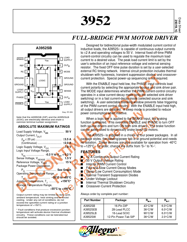
Data Sheet 29319.1C 3952 FULL-BRIDGE PWM MOTOR DRIVER A3952SB Designed for bidirectional pulse-width modulated current control of inductive loads, the A3952S– is capable ...
View more extracted text
modulated current control of inductive loads, the A3952S– is capable of continuous output currents to ±2 A and operating voltages to 50 V. Internal fixed off-time PWM BRAKE 1 REF 2 VBB 16 LOAD SUPPLY current-control circuitry can be used to regulate the maximum load current to a desired value. The peak load current limit is set by the 15 OUTB user’s selection of an input reference voltage and external sensing resistor. The fixed OFF-time pulse duration is set by a user-selected RC 3 14 MODE external RC timing network.