FEATURES
Input voltage range: 2.4 V to 5.5 V Low standby current: 1 µA Switching frequency: 3 MHz I2C interface Synchronous Buck 1 regulator: 600 mA Synchronous Buck 2 regulator: 250 mA Low dropout regulator (LDO): 150 mA Internal compensation Internal soft start Thermal shutdown 20-lead 4 mm × 4 mm LFCSP APPLICATIONS
Digital cameras, handsets Mobile TVs GENERAL DESCRIPTION
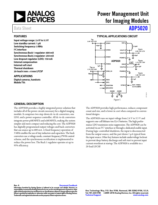
All dc-to-dc converters integrate power pMOSFETs and nMOSFETs, making the system simpler and more compact and reducing the cost. A fixed frequency operation of 3 MHz enables the use of tiny inductors and capacitors. The buck converters use a voltage mode, constant-frequency PWM control scheme, and the synchronous rectification is implemented to reduce the power loss. The Buck 1 regulator operates at up to 93% efficiency. Power Management Unit for Imaging Modules ADP5020 TYPICAL APPLICATIONS
CIRCUIT VIN 2.4V TO 5.5V VDD1 SW1 10µF 2.2µH 1µF VDD_IO 1.7V TO 3.6V 10kΩ 10kΩ 0.1µF VDD2 VOUT1 VOUT1 VDD3 PGND1 ADP5020 VDDA SW2 VOUT2 VDD_IO PGND2 SDA SCL XSHTDN EN/GPIO VOUT3 SYNC VOUT1 2.5V TO 3.7V 10µF VOUT2 2.2µH 1.1V TO 1.8V 4.7µF VOUT3 1.8V TO 3.3V 1µF EXT. Analog Devices