BNT
BNT is CIT SWITCH manufactured by CIT.
SPECIFICATIONS
Electrical Ratings Electrical Life Contact Resistance Dielectric Strength Insulation Resistance Operating Temperature Storage Temperature 3A @ 120VAC, 28VDC; 1A @ 250VAC See Contact Options 30,000 cycles typical < 20 mΩ max initial @ 2-4VDC, 100m A 1500Vrms min > 100MΩ min -40°C to 85°C -40°C to 85°C
MATERIALS ←Ro HS PLIANT
Actuator Housing Cover Bushing Contacts Terminals Brass, Chrome Plated DAP
- Diallyl Phthalate Stainless Steel Brass, Nickel Plated Copper Alloy, Silver or Gold Plated Brass, Silver or Gold Plated
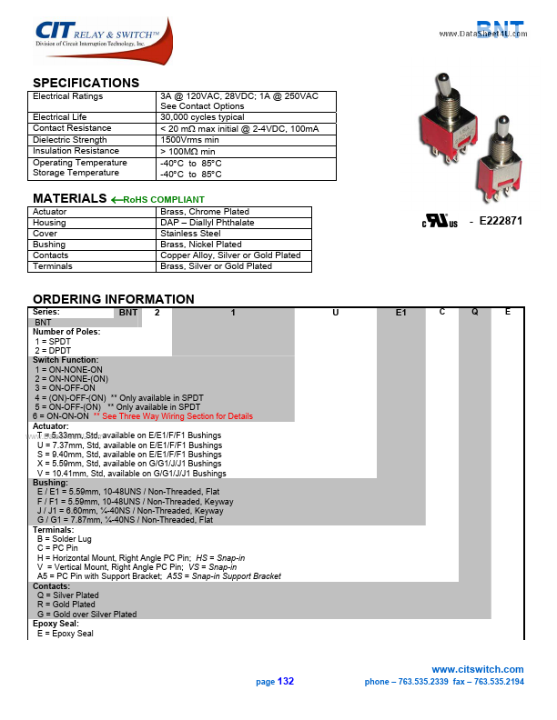
- E222871
ORDERING INFORMATION
Series: BNT 2 1 BNT Number of Poles: 1 = SPDT 2 = DPDT Switch Function: 1 = ON-NONE-ON 2 = ON-NONE-(ON) 3 = ON-OFF-ON 4 = (ON)-OFF-(ON)
- - Only available in SPDT 5 = ON-OFF-(ON)
- - Only available in SPDT 6 = ON-ON-ON
- - See Three Way Wiring Section for Details Actuator: T = 5.33mm, Std, available on E/E1/F/F1 Bushings .. U = 7.37mm, Std, available on E/E1/F/F1 Bushings S = 9.40mm, Std, available on E/E1/F/F1 Bushings X = 5.59mm, Std, available on G/G1/J/J1 Bushings V = 10.41mm, Std, available on G/G1/J/J1 Bushings Bushing: E / E1 = 5.59mm, 10-48UNS / Non-Threaded, Flat F / F1 = 5.59mm, 10-48UNS / Non-Threaded, Keyway J / J1 = 6.60mm, ¼-40NS / Non-Threaded, Keyway G / G1 = 7.87mm, ¼-40NS / Non-Threaded, Flat Terminals: B = Solder Lug C = PC Pin H = Horizontal Mount, Right Angle PC Pin; HS = Snap-in V = Vertical Mount, Right Angle PC Pin; VS = Snap-in A5 = PC Pin with Support Bracket; A5S = Snap-in Support Bracket Contacts: Q = Silver Plated R = Gold Plated G = Gold over Silver Plated Epoxy Seal: E = Epoxy Seal
E1
.citswitch. page 132 phone
- 763.535.2339 fax
- 763.535.2194
SWITCH FUNCTION
Toggle Position
Function
SPDT
1 2 3 4 5
Terminals
ON ON ON (ON) ON 2-3
NONE NONE OFF OFF OFF
ON (ON) ON (ON) (ON) 2-1
---
Toggle Position
Function
1 2 3
DPDT...