MAXIMUM RATINGS
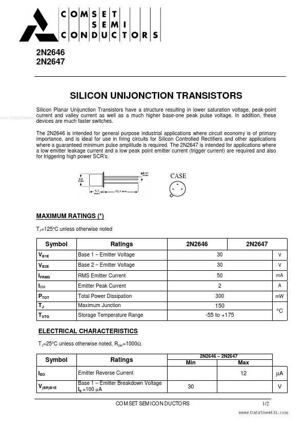
(*) TJ=125°C unless otherwise noted Symbol VB1E VB2E IFRMS IEM PTOT TJ TSTG Ratings Base 1 – Emitter Voltage Base 2 – Emitter Voltage RMS Emitter Current Emitter Peak Current Total Power Dissipation Maximum Junction Storage Temperature Range 2N2646 30 30 50 2 300 2N2647 V V mA A mW 150 -55 to +175 °C ELECTRICAL CHARACTERISTICS
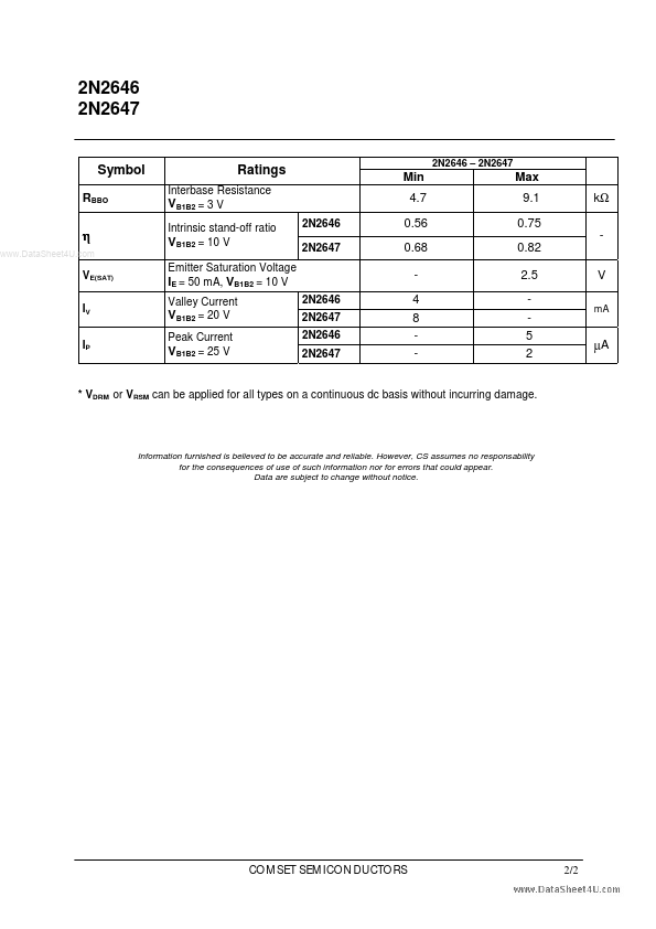
TJ=25°C unless otherwise noted, RGK=1000Ω Symbol IEO V(BR)B1E Ratings Emitter Reverse Current Base 1 – Emitter Breakdown Voltage IE =100 µA 2N2646 – 2N2647 Min Max 12 µA V 1/2 30 COMSET SEMICONDUCTORS 2N2646 2N2647 2N2646 – 2N2647 Symbol RBBO Ratings Interbase Resistance VB1B2 = 3 V Intrinsic stand-off ratio VB1B2 = 10 V Emitter Saturation Voltage IE = 50 mA, VB1B2 = 10 V Valley Current VB1B2 = 20 V Peak Current VB1B2 = 25 V 2N2646 2N2647 2N2646 2N2647 2N2646 2N2647 Min 4.7 0.56 0.68 4 8 - Max 9.1 0.75 0.82 2.5 5 2 V mA kΩ η VE(SAT) IV IP µA * VDRM or VRSM can be applied for all types on a continuous dc basis without incurring damage. Information furnished is believed to be accurate and reliable.