RC203
RC203 is TECHNICAL SPECIFICATIONS OF SINGLE-PHASE SILICON BRIDGE RECTIFIER manufactured by Dc Components.
FEATURES
- Surge overload ratings to 50 Amperes peak
- Ideal for printed circuit board assembly
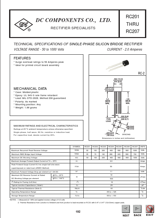
RC-2
MECHANICAL DATA
- -
- -
- - Case: Molded plastic Epoxy: UL 94V-0 rate flame retardant Lead: MIL-STD-202E, Method 208 guaranteed Polarity: As marked Mounting position: Any Weight: 1.88 grams
MAXIMUM RATINGS AND ELECTRICAL CHARACTERISTICS
Ratings at 25 o C ambient temperature unless otherwise specified. Single phase, half wave, 60 Hz, resistive or inductive load. For capacitive load, derate current by 20%. SPACING Dimensions in inches and (millimeters)
SYMBOL Maximum Recurrent Peak Reverse Voltage Maximum RMS Bridge Input Voltage Maximum DC Blocking Voltage Maximum Average Forward Output Current at T A = 25o C Peak Forward Surge Current 8.3 ms single half sine-wave superimposed on rated load (JEDEC Method) Maximum Forward Voltage Drop per element at 1.0A DC Maximum DC Reverse Current at Rated DC Blocking Voltage per element I t Rating for Fusing (t<8.3ms) Typical Junction Capacitance ( Note1) Typical Thermal Resistance (Note 2) Operating Temperature Range Storage Temperature Range NOTES : 1.Measured at 1 MHZ and applied reverse voltage of 4.0 volts
RC201 50 35 50
RC202 100 70 100
RC203 200 140 200
RC204 400 280 400 2.0 50 1.1 10
RC205 600 420 600
RC206 800 560 800
RC207 1000 700 1000
UNITS Volts Volts Volts Amps Amps Volts u Amps A 2 Sec p F
VRRM VRMS VDC IO I FSM VF IR
@T A = 25 o C @T A = 100 o C
500 I t CJ RθJ A TJ T STG
10 25 40 -55 to + 125 -55 to + 150
C/W
0 0
2. Thermal Resistance from Junction to Ambient and from junction to lead mounted on P.C.B. with 0.47 x 0.47" (12x12mm) copper pads.
NEXT NEXT NEXT
BACK BACK BACK
EXIT EXIT EXIT
RATING AND CHARACTERISTIC CURVES (RC201 THRU RC207)
DC PONENTS CO., LTD.
NEXT NEXT
BACK BACK
EXIT...