RC203
RC203 is SINGLE-PHASE GLASS PASSIVATED SILICON BRIDGE RECTIFIER manufactured by Rectron.
FEATURES
- -
- -
- - Reverse voltage to 1000v Surge overload ratings to 50 amperes peak Good for printed circuit board assembly Mounting position: Any Weight: 1.88 grams Silver-plated copper leads
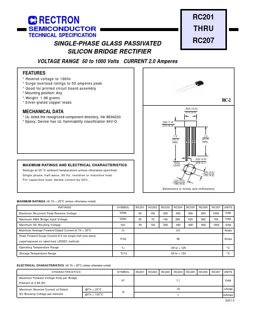
RC-2
.394 (10.0) .374 (9.5)
MECHANICAL DATA
- UL listed the recognized ponent directory, file #E94233
- Epoxy: Device has UL flammability classification 94V-O
.290 (7.4) .270 (6.9)
1.2 (30.5) MIN.
1.0 (25.4) MIN.
MAXIMUM RATINGS AND ELECTRICAL CHARACTERISTICS
Ratings at 25 o C ambient temperature unless otherwise specified. Single phase, half wave, 60 Hz, resistive or inductive load. For capacitive load, derate current by 20%.
POS. LEAD
.032 (0.8) .028 (0.7)
.220 (5.6) .180 (4.6) .220 (5.6) .180 (4.6)
Dimensions in inches and (millimeters)
MAXIMUM RATINGS (At T A = 25 o C unless otherwise noted) RATINGS Maximum Recurrent Peak Reverse Voltage Maximum RMS Bridge Input Voltage Maximum DC Blocking Voltage Maximum Average Forward Output Current at T A = 25o C Peak Forward Surge Current 8.3 ms single half sine-wave superimposed on rated load (JEDEC method) Operating Temperature Range Storage Temperature Range TJ T STG -55 to + 125 -55 to + 150
0 0
SYMBOL VRRM VRMS VDC IO I FSM
RC201 50 35 50
RC202 100 70 100
RC203 200 140 200
RC204 400 280 400 2.0 60
RC205 600 420 600
RC206 800 560 800
RC207 1000 700 1000
UNITS Volts Volts Volts Amps Amps C C
ELECTRICAL CHARACTERISTICS (At TA = 25o C unless otherwise noted) CHARACTERISTICS Maximum Forward Voltage Drop per Bridge Element at 2.0A DC Maximum Reverse Current at Rated DC Blocking Voltage per element @T A = 25 o C @T A = 100 o C SYMBOL VF RC201 RC202 RC203 RC204 1.1 10 IR 1 m Amps 2001-5 RC205 RC206 RC207 UNITS Volts u Amps
RATING AND CHARACTERISTIC CURVES ( RC201 THRU RC207 )
FIG. 2
- TYPICAL FORWARD CURRENT DERATING CURVE 2.0
AVERAGE FORWARD CURRENT, (A)
FIG. 1
- MAXIMUM FORWARD SURGE CURRENT
PEAK FORWARD SURGE CURRENT, (A)
8.3ms Single Half Sine-Wave (JEDED...