DMN601TK
DMN601TK is N-Channel MOSFET manufactured by Diodes Incorporated.
Features
NEW PRODUCT
- -
- -
- -
- -
Low On-Resistance: RDS(ON) Low Gate Threshold Voltage Low Input Capacitance Fast Switching Speed Low Input/Output Leakage Lead Free By Design/Ro HS pliant (Note 2) ESD Protected Up To 2k V "Green" Device (Note 4)
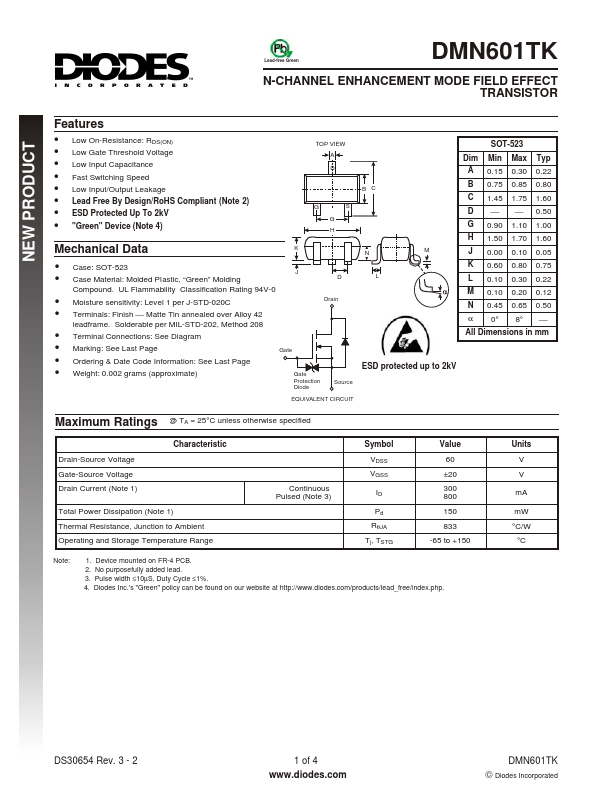
TOP VIEW A D B C G G H M S
SOT-523 Dim A B C D G H J K L M N α Min 0.15 0.75 1.45 0.90 1.50 0.00 0.60 0.10 0.10 0.45 0° Max 0.30 0.85 1.75 1.10 1.70 0.10 0.80 0.30 0.20 0.65 8° Typ 0.22 0.80 1.60 0.50 1.00 1.60 0.05 0.75 0.22 0.12 0.50
Mechanical Data
- -
- -
- -
- -
Case: SOT-523 Case Material: Molded Plastic, “Green” Molding pound. UL Flammability Classification Rating 94V-0 Moisture sensitivity: Level 1 per J-STD-020C Terminals: Finish Matte Tin annealed over Alloy 42 leadframe. Solderable per MIL-STD-202, Method 208 Terminal Connections: See Diagram Marking: See Last Page Ordering & Date Code Information: See Last Page Weight: 0.002 grams (approximate)
Gate
Drain
All Dimensions in mm
ESD protected up to 2k V
Gate Protection Diode Source
EQUIVALENT CIRCUIT
Maximum Ratings
Drain-Source Voltage Gate-Source Voltage Drain Current (Note 1)
@ TA = 25°C unless otherwise specified Characteristic Symbol VDSS VGSS Continuous Pulsed (Note 3) ID Pd RθJA Tj, TSTG Value 60 ±20 300 800 150 833 -65 to +150 Units V V m A m W °C/W °C
Total Power Dissipation (Note 1) Thermal Resistance, Junction to Ambient Operating and Storage Temperature Range
Note:
1. Device mounted on FR-4 PCB. 2. No purposefully added lead. 3. Pulse width ≤10µS, Duty Cycle ≤1%. 4. Diodes Inc.'s "Green" policy can be found on our website at http://.diodes./products/lead_free/index.php.
DS30654 Rev. 3
- 2
1 of 4 .diodes.
© Diodes Incorporated
Electrical Characteristics
@ TA = 25°C unless otherwise specified Symbol BVDSS IDSS IGSS VGS(th) RDS (ON) |Yfs| Ciss Coss Crss Min 60 1.0 80 Typ 1.6 Max 1.0 ±10 2.5 2.0 3.0 50 25 5.0 Unit V µA µA V Ω ms p F p F p F VDS = 25V, VGS = 0V f = 1.0MHz Test...