ELM310 Overview
Key Specifications
Length: 27.686 mm
Description
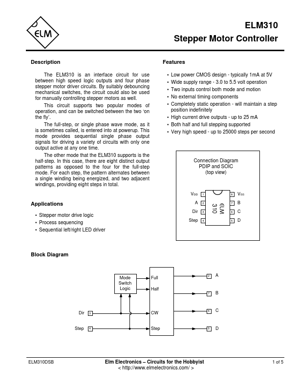
The ELM310 is an interface circuit for use between high speed logic outputs and four phase stepper motor driver circuits. By suitably debouncing mechanical switches, the circuit could also be used for manually controlling stepper motors as well.
Key Features
- Low power CMOS design
- typically 1mA at 5V
- Wide supply range
- 3.0 to 5.5 volt operation
- Two inputs control both mode and motion