Unknown Manufacturer L9110
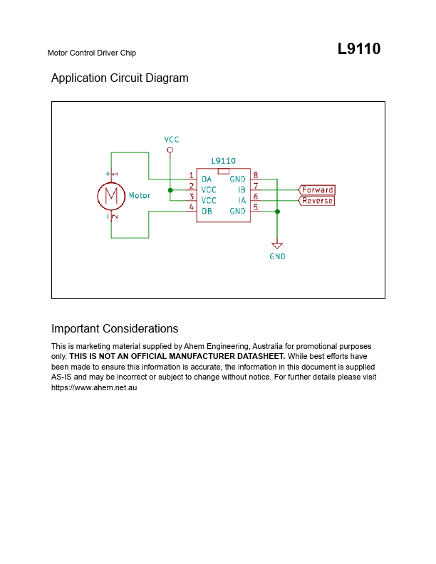
The L9110 is a two-channel push-pull amplifier circuit integrated into a monolithic IC with the required peripheral devices, reducing costs and improving the reliability. The two control inputs are TTL/CMOS compatible with high impedance. The two output terminals can directly drive motors in both forwards and reverse directions at up to 800 mA (1.5 - 2 A peak).| Part No. | L9110 |
|---|---|
| Datasheet | L9110 Download |
| Manufacturer | Unknown Manufacturer |
| Description | Motor Control Driver |
| Buy | Stock & Price |
FEATURES
:● Low quiescent current
● 2.5 - 12 VDC supply voltage range
● 800 mA continuous current, 1.5 - 2 A peak current
● TTL/CMOS input signal compatible
● Built in clamp diodes on output to prevent inductive kickback
● 0 - 80 °C Operating temperature
● Available in DIP8 and SOP8 Packages
DESCRIPTION
: The L9110 has a low output saturation voltage, built-in clamping diodes to protect against voltage spiking from the switching of inductive loads. The L9110 is widely used in toy car motor drives, stepper motor drives and switching amplifier circuits. PinDESCRIPTION
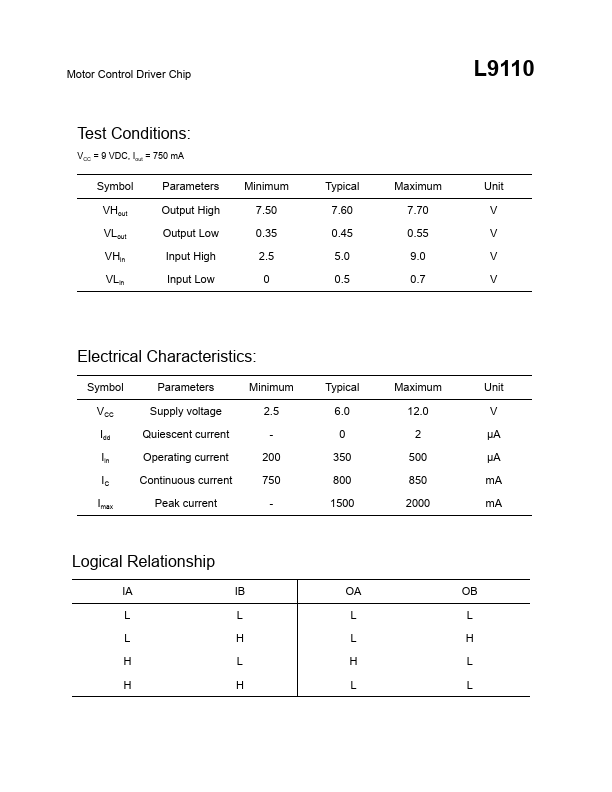
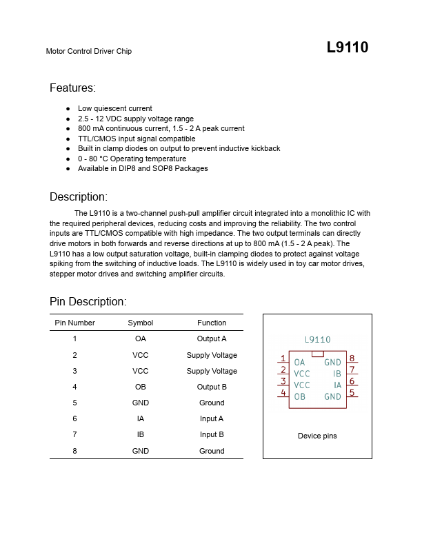
: Pin Number 1 2 3 4 5 6 7 8 Symbol OA VCC VCC OB GND IA IB GND Function Output A Supply Voltage Supply Voltage Output B Ground Input A Input B Ground Device pins Motor Control Driver Chip L9110 Test Conditions: VCC = 9 VDC, Iout = 750 mA Symbol Parameters Minimum Typical Maximum Unit VHout Output High 7.50 7.60 7.70 V VLout Output Low 0.35 0.45 0.55 V VHin Input High 2.5 5.0 9.0 V VLin Input Low 0 0.5 0.7 V Electrical Chara...