Datasheet4U Logo Datasheet4U.com

L9110S - Motor control drive IC

General Description

A Output pin Positive pole of power supply Positive pole of power supply B Output pin Power ground A Input terminal B Input terminal Power ground www.umw-ic.com 1 UMW R UMW L9110S Limit parameter Motor control drive IC project voltage ` symbo l VCC Vin explain Power supply voltage i

Key Features

  • The power supply range is 2.2~6.5V V.
  • Low static working current.
  • Low saturation pressure drop.
  • product usage.
  • TTL/CMOS output level is compatible and can be directly connected with CPU I/O.
  • Few external devices.
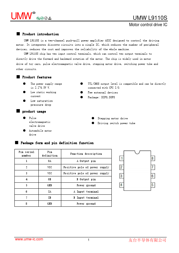
  • Package: DIP8,SOP8.
  • Pulse electromagnetic valve drive.
  • Automobile motor drive.
  • Stepping motor drive.
  • Driving switch power tube.
  • Package form and pin definition function Pin serial number 1 2 3 4 5 6 7 8 Pin definition.

📥 Download Datasheet

Datasheet Details

Part number L9110S
Manufacturer UMW
File Size 640.47 KB
Description Motor control drive IC
Datasheet download datasheet L9110S Datasheet

Full PDF Text Transcription (Reference)

The following content is an automatically extracted verbatim text from the original manufacturer datasheet and is provided for reference purposes only.

View original datasheet text
UMW R UMW L9110S Motor control drive IC ■ Product introduction UMW L9110S is a two-channel push-pull power amplifier ASIC designed to control the driving motor. It integrates discrete circuits into a single IC, which reduces the number of peripheral devices, reduces the cost and improves the reliability of the whole machine. UMW L9110S chip has two input control terminals, which can control two output terminals to directly drive the forward and backward rotation of the motor. The chip is widely used in motor drive of toy cars, pulse electromagnetic valve drive, stepping motor drive, switching power tube and other circuits. ■ Product features ● The power supply range is 2.2~6.5V V.