LCE20 Overview
Key Specifications
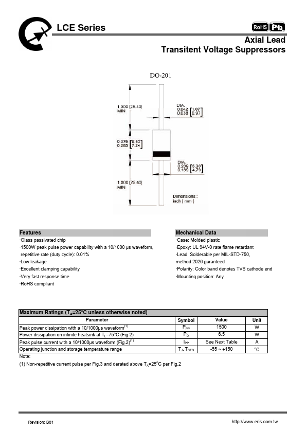
Mount Type: Through Hole
Operating Voltage: 20 V
Length: 9.5 mm
Max Operating Temp: 175 °C
| Part | LCE20 |
|---|---|
| Description | Transitent Voltage Suppressors |
| Manufacturer | Eris Technology |
| Size | 378.67 KB |
Mount Type: Through Hole
Operating Voltage: 20 V
Length: 9.5 mm
Max Operating Temp: 175 °C
| Seller | Inventory | Price Breaks | Buy |
|---|---|---|---|
| DigiKey | 632 | 1+ : 0.71 USD | View Offer |
| DigiKey | 0 | 1200+ : 0.27299 USD 2400+ : 0.25186 USD |
View Offer |
| Part Number | Manufacturer | Description |
|---|---|---|
| LCE20A | EIC discretes | LOW CAPACITANCE TRANSIENT VOLTAGE SUPPRESSOR |
| LCE20 | Microsemi | TRANSIENT ABSORPTION ZENER |
| LCE2009S | Philips Semiconductors | NPN microwave power transistors |
| LCE20A | General | LOW CAPACITANCE TRANSZORB TRANSIENT VOLTAGE SUPPRESSOR |
| LCE20A | Chip Integration Technology | 1500W Leaded Type Transient Voltage Suppressors |