FEATURES
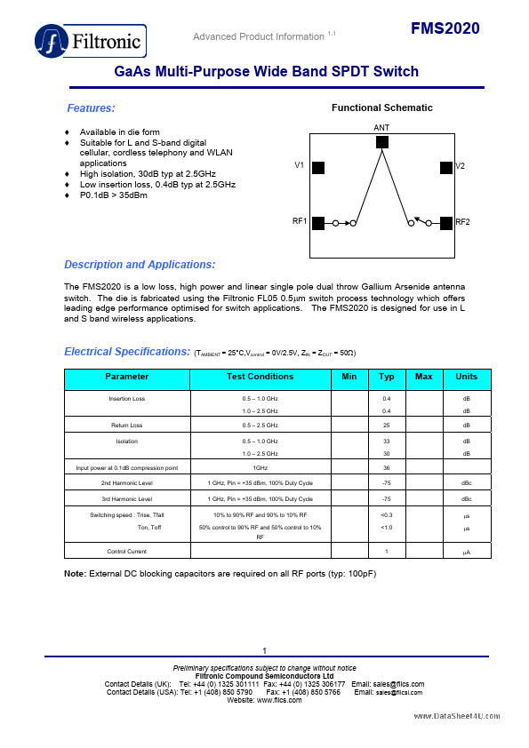
: ♦ ♦ ♦ ♦ ♦ Available in die form Suitable for L and S-band digital cellular, cordless telephony and WLAN applications High isolation, 30dB typ at 2.5GHz Low insertion loss, 0.4dB typ at 2.5GHz P0.1dB > 35dBm Functional Schematic ANT V1 V2 RF1 RF2 DESCRIPTION
and APPLICATIONS
: ELECTRICAL SPECIFICATIONS
: Parameter Insertion Loss (TAMBIENT = 25°C,Vcontrol = 0V/2.5V, ZIN = ZOUT = 50Ω) Test Conditions 0.5 – 1.0 GHz 1.0 – 2.5 GHz Min Typ 0.4 0.4 25 33 30 36 -75 -75 <0.3 <1.0 Max Units dB dB dB dB dB Return Loss Isolation 0.5 – 2.5 GHz 0.5 – 1.0 GHz 1.0 – 2.5 GHz Input power at 0.1dB compression point 2nd Harmonic Level 3rd Harmonic Level Switching speed : Trise, Tfall Ton, Toff 1GHz 1 GHz, Pin = +35 dBm, 100% Duty Cycle 1 GHz, Pin = +35 dBm, 100% Duty Cycle 10% to 90% RF and 90% to 10% RF 50% control to 90% RF and 50% control to 10% RF dBc dBc µs µs Control Current 1 µA Note: External DC blocking capacitors are required on all RF ports (typ: 100pF) 1 Preliminary specifications subje... Filtronic