FE2B
FE2B is GLASS PASSIVATED FAST EFFICIENT RECTIFIER manufactured by General Semiconductor.
FEATURES
- High temperature metallurgically bonded construction
- Glass passivated cavity-free junction
- Superfast recovery time for high efficiency
- Low forward voltage, high current capability
- Capable of meeting environmental standards of MIL-S-19500
- Hermetically sealed package
- Low leakage
- High surge capability
- High temperature soldering guaranteed: 350°C/10 seconds, 0.375" (9.5mm) lead length, 5 lbs. (2.3kg) tension
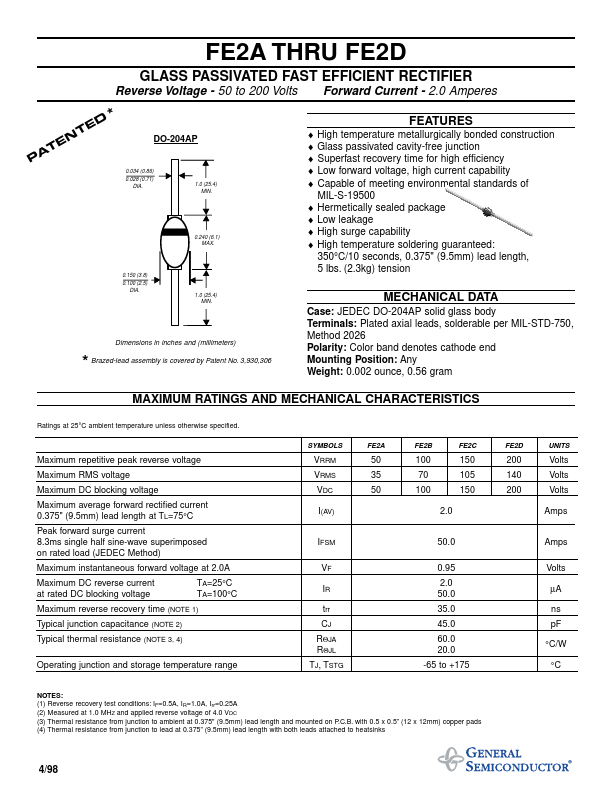
TE A P
0.034 (0.86) 0.028 (0.71) DIA. 1.0 (25.4) MIN.
0.240 (6.1) MAX.
0.150 (3.8) 0.100 (2.5) DIA.
1.0 (25.4) MIN.
MECHANICAL DATA
Case: JEDEC DO-204AP solid glass body Terminals: Plated axial leads, solderable per MIL-STD-750, Method 2026 Polarity: Color band denotes cathode end Mounting Position: Any Weight: 0.002 ounce, 0.56 gram
Dimensions in inches and (millimeters)
- Brazed-lead assembly is covered by Patent No. 3,930,306
MAXIMUM RATINGS AND MECHANICAL CHARACTERISTICS
Ratings at 25°C ambient temperature unless otherwise specified.
SYMBOLS
FE2A
FE2C
FE2D
UNITS
Maximum repetitive peak reverse voltage Maximum RMS voltage Maximum DC blocking voltage Maximum average forward rectified current 0.375" (9.5mm) lead length at TL=75°C Peak forward surge current 8.3ms single half sine-wave superimposed on rated load (JEDEC Method) Maximum instantaneous forward voltage at 2.0A Maximum DC reverse current at rated DC blocking voltage Typical junction capacitance (NOTE 2) Typical thermal resistance (NOTE 3, 4) Operating junction and storage temperature range TA=25°C TA=100°C
VRRM VRMS VDC I(AV)
50 35 50
100 70 100 2.0
150 105 150
200 140 200
Volts Volts Volts Amps
IFSM VF IR trr CJ RΘJA RΘJL TJ, TSTG
50.0 0.95 2.0 50.0 35.0 45.0 60.0 20.0 -65 to +175
Amps Volts µA ns p F °C/W °C
Maximum reverse recovery time (NOTE 1)
NOTES: (1) Reverse recovery test conditions: IF=0.5A, IR=1.0A, Irr=0.25A (2) Measured at 1.0 MHZ and applied reverse voltage of 4.0 VDC (3) Thermal resistance from junction to ambient at 0.375" (9.5mm)...