CD4017 Overview
Key Specifications
Package: SOP
Mount Type: Surface Mount
Pins: 16
Max Voltage (typical range): 18 V
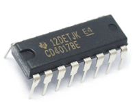
Representative CD4017 image (package may vary by manufacturer)
Description
Pulse width modulation circuit CD4017 is a 5th order Johnson decoding counter with 10 decoding outputs, CLOCK, RE, INH inputs, and a Schmidt trigger with pulse shaping function at the clock input, which has no limit on the rise and fall time of input clock pulses. INH is low level, and the counter counts on the rising edge of the clock; On the contrary, the counting function is invalid.