DESCRIPTION
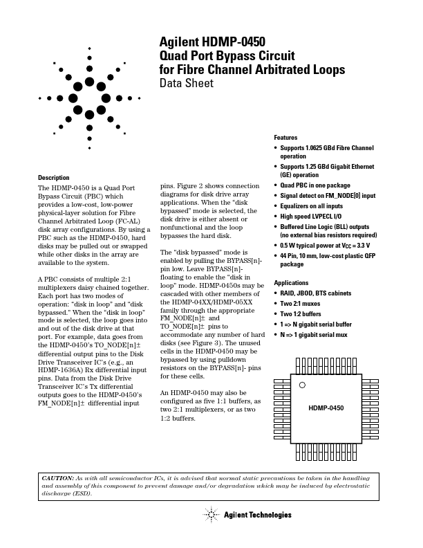
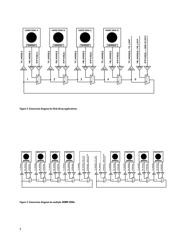
A PBC consists of multiple 2:1 multiplexers daisy chained together. For example, data goes from the HDMP-0450’s TO_NODE[n] ± differential output pins to the Disk Drive Transceiver IC’s (e.g., an HDMP-1636A) Rx differential input pins. Data from the Disk Drive Transceiver IC’s Tx differential outputs goes to the HDMP-0450’s FM_NODE[n] ± differential input pins. Figure 2 shows connection diagrams for disk drive array applications. When the “disk bypassed” mode is selected, the disk drive is either absent or nonfunctional and the loop bypasses the hard disk. The “disk bypassed” mode is enabled by pulling the BYPASS[n]pin low. Leave BYPASS[n]floating to enable the “disk in loop” mode. HDMP-0450s may be cascaded with other members of the HDMP-04XX/HDMP-05XX family through the appropriate FM_NODE[n]± and TO_NODE[n]± pins to accommodate any number of hard disks (see Figure 3). The unused cells in the HDMP-0450 may be bypassed by using pulldown resistors on the BYPASS[n]- pins for these cells. Hewlett-Packard