HD74HC158 Overview
| Part | HD74HC158 |
|---|---|
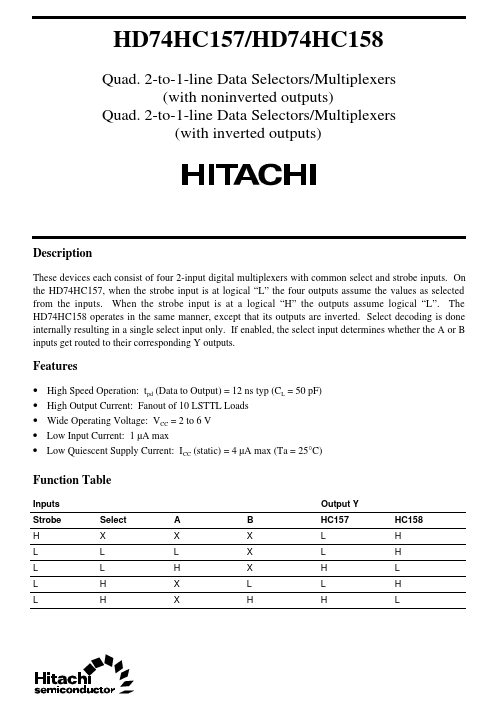
| Description | These devices each consist of four 2-input digital multiplexers with common select and strobe inputs |
| Manufacturer | Hitachi Semiconductor |
| Size | 57.39 KB |
| Part Number | Manufacturer | Description |
|---|---|---|
| HD74HC158 | Renesas | Quad. 2-to-1-line Data Selectors / Multiplexers |
| HD74HC153 | Renesas | Dual 4-to-1-line Data Selectors/Multiplexers |
| HD74HC152 | Renesas | 1-of-8-line Data Selector/Multiplexer |
| HD74HC151 | Renesas | 1-of-8-line Data Selector/Multiplexer |
| HD74HC155 | Renesas | Dual 2-to-4-line Decoders/Demultiplexers |